Designing Pipes for Detonations
A lesson from the Fukushima Dai-Ichi accident – The series of events that followed the March 11, 2011 tsunami caused hydrogen explosions that damaged the reactor buildings of three units at Fukushima Dai-ichi. In June 2013, the US NRC issued order EA-13-109 “Order to Modify Licenses with Regard to Reliable Hardened Containment Vents Capable of Operation Under Severe Accident Conditions”. This order requires BWR plants with Mark I or Mark II containments “to implement requirements for reliable hardened containment vents capable of operation under severe accident conditions at their facilities.” Among other things the order requires that the hardened containment vent systems (HCVS) be designed and operated to prevent the accumulation of explosive mixtures of gases, or “otherwise, the system shall be designed to withstand dynamic loading resulting from hydrogen deflagration and detonation.”
NEI Guidance – In order to coordinate the resolution of the NRC’s EA-13-109, the Nuclear Energy Institute (NEI) issued NEI 13-02 “Industry Guidance for Compliance with Order EA-13-109, BWR Mark I & II Reliable Hardened Containment Vents Capable of Operation Under Severe Accident Condition”. The NEI Guidance covers several topics related to NRC order EA-13-109, and in particular: (1) The prevention of detonation, or alternatively (2) The design of the hardened containment vent system (HCVS) to sustain the detonation. For the design of the HCVS to sustain detonations the NEI 13-02 Guidance states:
Section 2.4.7: “The piping, valves, and the valve actuators should be designed to withstand the dynamic loading resulting from the actuation of the system, including piping reaction loads from valve opening, resultant loads from SRV operation, potential for water hammer from accumulation of steam condensation, and hydrogen detonation, if applicable, during multiple venting cycles.” Section 4.1.6.1.1.2 provides further clarification regarding the cause of the detonation event, as being a “deflagration/detonation due to potential for oxygen intrusion resulting from steam condensation following HCVS vent closure”. The criteria for design are stated in Section 4.1.7 as “Deformation of the pipe is acceptable given the integrity and continued functional capability of the vent system is shown to be maintained” and are expanded in Appendix H.
Detonation analysis plan – Where the potential for explosion cannot be fully discarded, the HCVS must be qualified to sustain postulated detonations, as stated in the NRC Order EA-13-109, and the NEI Guidance 13-02. These two documents are good starting points for the detonation analysis and qualification process. From there, a more detailed analysis and qualification plan can be developed, as described here.
Four-Step process – The analysis of detonations in piping systems entails four essential steps, which we will discuss here:
(1) Step 1: Initial Conditions – The initial conditions of the gas mixture are important because they will determine the type of explosion to be analyzed (deflagration, detonation, transition from deflagration to detonation, reflected detonation). These initial conditions include the gas mixture, the initial gas pressure and temperature, the level of humidity inside the vent pipe, the ignition source, the geometry of the pipe, the possible reflection surfaces (either solid or liquid), etc. An important aspect of the initial conditions is to define how many explosions can take place: is it a single event or can it happen multiple times. In case of multiple explosions, and unless the pipe remains elastic under detonation, there would be a strain accumulation effect and a fatigue effect that would render the mechanical analysis (Step 3) and the qualification (Step 4) more difficult.
(2) Step 2: Gas Dynamics: The gas dynamics analysis, which calculates the pressure time-history of the detonation P(t).
(3) Step 3: Stress and Strain Analysis: The mechanical integrity analysis which calculates the load-stress-strain response of the piping system.
(4) Step 4: Qualification: The qualification assessment, which combines the detonation with concurrent loads, and compares the results of the mechanical integrity analysis to qualification load-stress-strain limits.
References – There are several references that the engineer should study before embarking on a detonation analysis, these include:
1. The work done over several years at the California Institute of Technology on the gas dynamics of detonations, and which NEI 13-02 Appendix H references.
2. The body of work sponsored by the US Department of Energy, first at the Savannah River Site, and more recently at Hanford as part of the waste treatment plant (WTP) project. The DOE-sponsored work addressed both the gas dynamics and the mechanical stress-strain analysis aspects of the problem.
3. The ASME VIII Div.3 Code Case 2564 “Impulsively Loaded Pressure Vessels, Section VIII Div.3”, which addresses the stress-strain and fracture analysis rules for pressure vessels subject to single or multiple detonations.
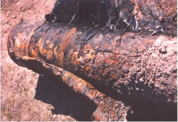
4. The two precedents of detonations inside pipes in nuclear power plants, On November 7th, 2001, the detonation of a hydrogen-oxygen mixture, caused by radiolysis, at Hamaoka-1 in Japan, and Brunsbuttel KBB in Germany, on December 14, 2001. In both cases, the pipes fractured, as indicated in the photographs. These events are documented in several publications, and hydrogen explosions are addressed in the US NRC Generic Safety Issue 195: Hydrogen Combustion in BWR Piping ( NUREG-0933, Main Report with Supplements 1–34 ).
5. The many publications on the subject of detonation in steel pipes and vessels, many of them published through the ASME Pressure Vessel and Piping (PVP) conference proceedings.
6. The textbooks on the subject of explosions, such as “Gas, Dust, and hybrid Explosions” by W.E. Baker and M.J. Tang; “The Detonation Phenomenon” by J.H.S. Lee; “Shock, Impact and Explosion: Structural Analysis and Design” by M.Y.H. Bangash.
So, the challenge is to take all of the above knowledge and streamline it into an analysis and qualification specification that can be applied to the HCVS. This can be done if we divide the problem into its four components, as mentioned earlier: (1) the initial conditions, (2) the gas dynamics analysis, (3) the mechanical integrity stress-strain analysis, and (4) the qualification. We will address these briefly here.
The initial conditions and the gas dynamics – For the HCVS the objective of the gas dynamics analysis is to develop the forcing function P(t) of the detonation. To achieve this objective, we need to know several key initial parameters: The initial gas mixture, the initial pressure and temperature, the initial humidity, the ignition source and location, the geometry of the pipe, the run-up distances, and the potential for reflections at closed or partially closed ends. The outcome of the gas dynamics analysis is the pressure forcing function P(t) for the several types of explosions that can take place: deflagration, deflagration-to-detonation transition (DDT), reflected DDT, and reflected detonation. Also, as part of the gas dynamics analysis, the system engineer must define the potential number of explosion events. Is it a single event or multiple events, and if multiple do they have identical initial conditions?
The mechanical-structural analysis – Having developed the forcing function P(t), the piping system is analyzed for two effects: (a) A membrane (breathing) effect and (b) a beam effect. The membrane effect consists of the dynamic hoop (radial expansion) effect of the pressure, which results in hoop stresses and also in longitudinal stresses caused by the ringing of the pipe wall. The beam effect is somewhat similar to a waterhammer in that the piping system is subjected to the time-dependent longitudinal forces caused by the pressure imbalance of the passing shock wave. The beam effect induces stresses in the pipe as well as reaction loads on the supports.
Impulsive or quasi-static load? – An important aspect of the mechanical-structural analysis is to understand from the outset whether the applied detonation load P(t) acts in an impulsive manner or in a quasi-static manner. An impulsive load is a load that is much shorter than the natural frequency of the pipe, in the mode of deformation. For example CC 2564 defines an impulsive load as a load that has duration “less than 35% of the fundamental, membrane-stress dominated (breathing) mode.” In the case of piping systems, we have to check the impulsive aspects of both the breathing mode and the beam mode. In the case of an impulsive load, the damage is not proportional to the peak pressure, rather it is a function of the impulse i.e. the area under the pressure-time curve P(t). Otherwise, if the duration of the peak pressure is sufficiently long, the load is quasi-static and the response (stress-strain) of the pipe is a direct function of the peak pressure.
Load Combination and Qualification – The load combination for the detonation design of the HCVS piping system is addressed in Appendix H of the NEI Guide. The detonation load is combined with concurrent loads i.e. deadweight labeled D, and the “most critical thermal load (assumed to be the effluent temperature)” labeled To. The NEI Guide then refers to ASME III ND-3654.1 and Service Level C stress limits for multiple events. In fact there are other checks that need to be taken into consideration, beyond ND-3650: The limits on hoop stress or strains, the limits on ringing stresses or strains, the limits on beam stresses (in this case ND-3650 would apply), and the fatigue accumulation of stress or strain cycles if the response is plastic. Separately, for the piping, the thermal stress would be checked, and then the total load would be applied to the supports. If essential active valves or in-line instruments are present, they would have to be qualified for the detonation pressure and temperature, and the detonation-induced accelerations. Note that in an impulsive load the impulse accelerations can be large, but of high frequency and therefore small deflections.
In summary – The analysis of the HCVS piping system for postulated single or multiple detonations should start with an analysis and qualification plan, which addresses the four aspects of the work: (1) the initial conditions, (2) the gas dynamics and resulting forcing functions P(t), (3) the mechanical response analysis which must address the membrane and beam effects, and (4) the load combination and qualification criteria, which must address membrane and ringing stress or strain limits, beam effects stress or strain limits, fatigue usage and strain accumulation for multiple events, in-line components pressure and acceleration limits. The NEI Guide 13-02 Appendix H, is a starting point.
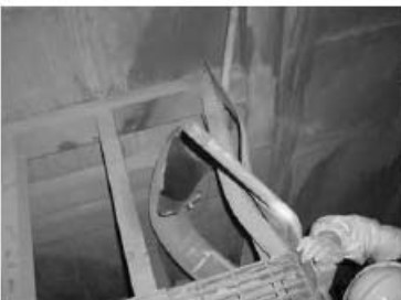
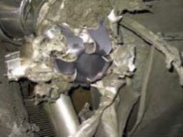
Hydrogen Detonation in Pipe at Hamaoka-1 (Top) and Brunbsuettel (Bottom)