Evaluation of Corroded Pipe in Accordance with ASME B&PV Code Section XI – A Comparison of the Three Code Cases
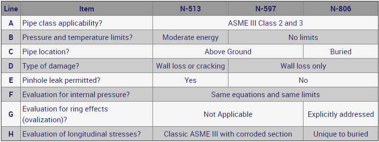
The evaluation of wall thinning corrosion in steel pipes is addressed in three ASME XI code cases: N-513, N-597, and N-806. I have no ambition here other than to summarize in a table the differences between these three code cases. A brief commentary follows the table.
The brief commentary…
- Line A –
- While these are Section XI Code Cases applicable to ASME III Class 2 and 3, technically, nothing would prevent from applying these Code Cases for B31.1 piping.
- Line B –
- There is no technical basis for limiting N-513 to moderate energy lines, i.e. pressure at or below 275 psi and (“or”, depending on the plant vintage) temperature at or below 200oF, other than the understandable reluctance to operate with hot water flashing to steam through a pinhole leak.
- Line D –
- It can be confusing that N-513 includes fracture mechanics consideration because it attempts to address cracks (so-called “planar flaws”) in addition to wall thinning. It may have been wiser to have a separate Code Case for crack-like defects. But it is what it is.
- Line E –
- N-597 explicitly prohibits, in the text, corrosion that has progressed through the wall (leaking pipe). N-806 does too, but N-806 adds two corroded wall limits to reflect this prohibition: A minimum wall of 0.10 in., and (with one exception) a minimum wall of 20% of nominal.
- Line F –
- Many engineers do not realize that the adequacy of a corroded pipe for internal pressure, i.e. preventing the burst of the corroded region, follows the same equations and limits in all three code cases. This is, of course, logical since the burst capacity is independent of burial or internal pressure and temperature.
- Line G –
- The potential for ovalization of the corroded region would be caused by large surface traffic, or heavy backfill. It is unique to buried pipes.
- Line H –
- While the longitudinal stress formula is the same for above-ground and buried pipe (along the lines of PD/4t and iM/Z), the loads that cause the bending moments M are quite different. For an above-ground pipe M is caused by inertia or thermal expansion. For buried pipe M is caused by things like ground settlement, flooding, seismic wave passage, or constrained thermal expansion.