Origins and Fates of Chlorides in Hydroprocessing Units – Part 2: Magnitude and Source(s) the Problem

The first article of this series introduced the symptoms of a chloride problem in a hydroprocessing unit. In this article, we will explore how to interpret the symptoms by determining how much chloride-containing material we are looking for and identifying the possible or likely source(s) for this amount of material, embodied in Steps 2 and 3 of the problem analysis.
Step 2 – How Big is the Problem?
It is very helpful to know the magnitude and type of the chloride problem before you go looking for a possible source. Start by chemically analyzing selected streams for chlorides. Be sure your operators use good industrial hygiene practices (e.g. chemical gloves) in sampling streams for chlorides since most chloride compounds are hazardous, even in the low concentrations we are testing.
- Analyze the hydroprocessing unit feed. Determine the total chloride content of the feed and the split between inorganic and organic chlorides. There are multiple methods available for determining feed chlorides:
- X-ray can be used to determine the chloride content of most hydrocarbon streams down to less than 3 ppm. This method is useful and fast for normal chloride analyses.
- Wet chemical methods based on potentiometric titration with methanol and ion chromatography are also available. These are accurate to less than 1 ppm, but require considerably longer to run than the x-ray.
- Newer instrumental analysis methods are continually improving chloride determination. Methods for determining individual chloride compounds down to less than 0.01 ppm in feedstocks are available.
- The split between inorganic and organic chlorides can be determined by water washing the feed. Then analyze the wash water and the remaining oil for chloride separately.
- Detailed speciation of the organic chlorides is available. This is a huge help in finding or eliminating possible sources. This service is available from several of the common third-party labs.
- Analyze the feed for Bottom Sediment and Water (BS&W) to get an idea of how much inorganic salts may be entering.
- Analyze the sour wash water. Determine the chloride content of the spent sour wash water from the high pressure separator and the stripper overhead, if used.
- Analyze the chlorides in the crude unit. Crude assays indicate salt content of the crude in pounds per thousand barrels. This is a good starting point. The crude salts are usually determined by a simple device like the “Nalcometer” based on conductivity using a calibration reference. For more detail, look at the inorganic and organic chlorides in the crude before and after the desalters. Look at the chloride contents of any slops or recovered oil streams sent to the crude unit. Detailed organic chloride speciation and analyzing for sodium, calcium, and magnesium may help here. If the chloride problem is in a specific boiling range, you can make a rough heartcut of that boiling range of the crude and look at the chlorides in that cut specifically.
- Analyze the chlorides in the makeup hydrogen. Test for HCl in the makeup hydrogen. Normally, this is done using a Dräger tube or similar test method. This may not be accurate if your chloride adsorbers are saturated, in which case you need to use another method to look for organic chlorides (or better yet, change your adsorbents).
From the feed analysis results and known or estimated flow rates, you can estimate the amount of chloride coming into the hydroprocessing unit. Consider a 50,000 bpd diesel hydrotreater with a 40°API feed containing 5 ppm organic chloride. The total incoming organic chloride is:
50,000 bpd x 288.6 lb/bbl x 5×10⁻⁶ parts Cl = 72 lb/day chloride
Using the spent wash water analyses, suppose you have 50 gpm wash water (once through) to our 50,000 bpd diesel hydrotreater. The concentration expected in the spent wash water would be about:
(72 lb/day Cl) / (50 gal/min x 1440 min/day x 8.34 lb/gal) x 106 = 120 wppm Cl in water
If you recycle water for phase control or use stripped sour water, you need to account for any chloride coming in with the water when making the above calculations.
You could also get at an estimate of how much material you are looking for by taking the 72 lb/day chloride and assuming it was PERC. This would imply a PERC contamination of about 6.2 gallons per day.
Looking at the hydrogen makeup stream analyses, you can estimate how much chloride is entering from this source fairly easily using the concentration of chlorides (usually in vppm) and the makeup gas rate. If you have 1.5 vppm chloride in 700 scf/bbl reformer hydrogen makeup at 50,000 bpd, the makeup hydrogen is bringing in:
50,000 bpd x 700 scf/bbl x 1.5×10⁻⁶ ppm HCl = 52.5 scf/day chloride
52.5 scf/day ÷ 379.45 scf/mol x 35.5 lb/mol = 4.9 lb chloride/day
For deposits of chlorides in exchangers or the reactors, you can estimate the mass of chloride in the deposits from the analyses. You then can make some assumptions about how much mass of deposit that represents. Note that for ammonium chloride deposits, both the chloride and nitrogen are needed. So, for instance, if you have a naphtha with 5 ppm chloride, but only 1 ppm nitrogen, the amount of deposit possible is limited by the nitrogen, not the chloride. 1 wppm nitrogen can make, at most, 3.8 ppm NH4Cl deposit before running out of nitrogen. In fact, you won’t get even that much as deposition occurs and partial pressures drop. The excess chloride will go to lower the pH of any effluent water. You get some effluent fouling, along with a corrosion bonus!
From observations and experience, the density of the fouling deposits tends to be on the order of 20-30 lb/cft, regardless of what the foulant is. Suppose we have our diesel hydrotreater with 72 lb/day of chloride and it has more than enough nitrogen for all the chloride to deposit as a NH4Cl in the effluent. The amount of deposit expected would then be about:
72 lb Cl/day x 53.5 lb NH4Cl / 35.5 lb Cl ÷ 25 lb/cft (avg) = 4.3 cft/day of NH4Cl deposits
Another approach to determining the amount of material you are looking for is to perform chloride balances around the upstream units. This can be one of the best tools for identifying the source and magnitude of a chloride problem at the same time. Pay particular attention to the desalters and reforming and isomerization units. Develop a good material balance and sample all streams for chlorides. With attention to detail, an acceptable (+/-2%) chloride balance is achievable.
Once you have an idea of how much chloride you are looking for, you can begin considering possible sources for the material.
Step 3 – Identify the Sources
As you could surmise from the analytical testing above, chlorides in hydroprocessing units enter generally via two routes:
- Feedstock
- Reformer Hydrogen Makeup
We now have an idea of how much material we are looking for, so we can start looking at the possible sources in more detail. From experience, the most common source(s) for chloride problems are internal to a refinery. Outside crude contamination can still occur occasionally, however; so don’t rule it out too early.
Feedstock Chloride Sources
Naphtha Reforming and Isomerization Units
Chloride is used in both reformers and isomerization units to maintain catalyst activity. We are going to focus here on how chloride can get into a hydroprocessing unit liquid feed from one of these units. We will talk later about the reformer hydrogen route.
Chloriding agents are used to provide the necessary chloride to a reformer or isomerization unit. The agents are mixed with naphtha and injected into the unit. Agents which have been used have included trichloroethylene (TCE, C2HCl3), perchloroethylene (PERC, C2H4), and carbon tetrachloride (CCl4). PERC is most common and carbon tetrachloride is no longer used due to toxicity. PERC has also been used for dry cleaning and equipment cleaning. These materials convert completely to yield HCl in the processes normally. Key properties of some of these chemicals are listed in Table 1.
Table 1 Properties of Chloriding Agents
|
Chemical |
Perchloroethylene |
Trichloroethylene |
Carbon Tetrachloride |
| Nickname | PERC | TCE or Trike | |
| Formula | C2Cl4 | C2HCl3 | CCl4 |
| Molecular Weight | 165.8 | 131.4 | 153.8 |
| Boiling Point, °F | 250 | 189 | 170 |
| Density, g/cm3 | 1.622 | 1.46 | 1.5867 |
| Density, lb/gal | 13.5 | 12.2 | 13.2 |
| Solubility in Water | 0.15 g/L | 1.28 g/L | 0.81 g/L (25°C) |
| w% Chlorine | 85.6 | 81.1 | 92.3 |
| Health Effects | Toxicity moderate to low | Carcinogenic | Very toxic |
| NFPA Ratings, H-F-R | 2-0-0 | 2-1-0 | 3-0-1 |
Chloriding agents can enter hydroprocessing unit feedstocks by several, unintended routes. Observed contamination routes from reformer and isomerization operations have included:
- Leaks or drainings from the chloriding agent storage drums or systems
- Overflow of chloriding agent drums to sewer or flare
- Poor chloriding agent receiving practices (such as draining residual material from a truck into the sewer)
The agents that reach the sewer or flare end up in the slops or recovered oil systems and are charged back to the crude unit. They then normally distill into the naphtha heading to the reformer pretreater.
Crude Oil
Salt is a natural part of crude oil. A certain amount of brine is co-produced with crude. The brine is separated in the field and the relatively dry crude oil is sent to the refinery. Chloride introduced into a well during a workover or well-stimulation effort will also appear in the produced crude. During transportation, brine can enter crude oil from seawater. Regardless of the origin, the crude salts can be a source of chlorides in hydroprocessing unit feeds. The salts consist primarily of sodium, magnesium and calcium chlorides. As a rule, the less polar the salt, the less soluble it will be in water and the more soluble it is in the crude. The crude will tend to hang on to magnesium and calcium chlorides, even through desalting. Sodium salt removal by desalting is usually complete. Fortunately, the normal levels of Mg and Ca chlorides in crudes are low. But some crudes have more than others.
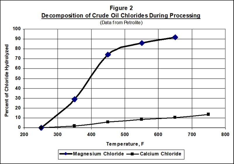
As crude is processed through the primary crude unit, vacuum unit, and coker, residual magnesium or calcium chlorides will begin to hydrolyze in the presence of trace water, releasing HCl(1,2). The hydrolysis relationship to temperature is illustrated in Figure 2, with data published by Petrolite(3). Sodium chloride will not decompose to any significant extent. HCl generated from the magnesium and calcium salts will move upward in the distillation columns until it finds ammonia or amines to combine with, or until a liquid water phase forms, or until the HCl gets drawn into a product. There the chlorides’ effects will be evident in the columns or exchangers for the crude, vacuum, and/or coker units.
A key control on crude unit inorganic chlorides is desalting efficiency. Most desalters can remove 90-95% of the salts from the incoming crude in a single stage. This salt will mostly be sodium chloride. A lot of the magnesium and calcium chlorides stay in the desalted crude. For a crude with 20 lb per thousand barrels (ptb) salt, the product salt will be less than 2 ptb. This is not really a problem level. If the crude salt level rises to 200 ptb, however, and the crude has more magnesium and calcium salts, the desalter may only produce 20 ptb product. This is a lot of salt to leave in the crude unit charge, even when only some is Mg and Ca.
Organic chlorides are not naturally present in crude oils. A crude organic chloride source that has been frequently observed is the blending of organic solvents (e.g. PERC dry cleaning solvent) into the crude for disposal. This is often difficult to trace back to a specific crude source. Some refiners have set specifications for maximum organic chlorides in crude (or in the naphtha fraction of crude) that they are willing to purchase. Such solvents would usually distill into the naphtha streams and react in the naphtha hydrotreaters to release HCl.
Other Upstream Units
Residual chlorides from upstream units often end up in hydroprocessing unit feeds. For instance, chlorides in a coker fractionator will be present in every product stream. Depending on the operating conditions for a given column, chlorides will distribute across the full range of distillation products. A chloride balance around each upstream unit, although difficult, helps indicate where a problem condition exists. These chlorides may include various organic compounds resulting from the reaction of HCl with olefins.
Water and nitrogen play roles in determining where chlorides come out of fractionation units. Most chlorides are very soluble in water, so any chloride formed by decomposition in a still will move up a column until liquid water forms. Some of the chloride will partition to the oil, in equilibrium with the water phase. While we might usually ignore HCl dissolved in oil, when you are worried about parts per million of chloride, the solubility is important. Nitrogen compounds, such as amines, also hold on to chloride, acting as bases. Some nitrogen compounds are specifically designed to pull inorganics into the oil phase. Crudes high in nitrogen will tend to produce gas oils high in nitrogen, which will carry chloride into downstream hydroprocessing systems.
Even within the upstream units, operating conditions for columns can increase or decrease chloride contents of streams. Manipulating column pressures, temperatures and reflux rates can greatly affect how the chlorides will partition among the product streams.
In some instances, very heavy crudes may be charged directly to a coker. These heavy crudes are generally not desalted and have not been separated well from production brines. Crude chlorides are thus introduced directly into the coker, often at the fractionator. The resulting coker products have concentrations of chloride and will even contain organic chlorides formed from reactions between HCl and olefins in the coker products.
Potentially major sources (or accumulation locations) for organic chlorides within a refinery are the recovered oil and slops systems. These streams are often charged to the crude unit to save the hydrocarbon value of the streams. Organic chlorides can enter these systems from many sources, including:
- Reformer or isomerization unit chloriding agents as previously described
- Skimmings from the sour water drums or tanks from a contaminated system
- Spent maintenance solvents sent into the system
- Receiving solvents from an outside source for disposal
- Waste water treatment plant recovered oil or sludge
When recovered or slop oil contaminated with organic chlorides is re-run in the crude unit, the organic chlorides distribute into the products according to their boiling points. It can be extremely difficult to identify the source(s).
Contamination of a refinery sewer system with organic chlorides can be a particularly difficult issue to identify. Because the compounds involved are not very water soluble, are only mildly volatile, and are heavier than water, they can lay in the sewer seal boxes and other low points, quiescent locations, until high flow rates entrain the material out of the low points or a hydrocarbon dissolves them out. They may then show up all at once or in spikes. Similar issues can make identifying a chloride source difficult when the materials are moving through the sour water or flare systems.
Reformer Hydrogen Makeup
The most common gaseous source of chloride in hydroprocessing units is naphtha reformer hydrogen. There is always a trace of chloride (as HCl) in any naphtha reformer or isomerization unit net hydrogen production. When this offgas is introduced into a hydroprocessing unit as makeup hydrogen, the chloride goes too.
The chloride level in reformer hydrogen is normally very low – about 1-3 vppm. It is often managed by passing the net reformer hydrogen through a chloride adsorber. When the adsorbent is spent, it will allow chloride to slip; but the resulting material released is an organic chloride polymer (AKA “green oil”, not HCl. This was alluded to in the analytical discussion above.
An isomerization unit maintains a higher level of HCl in the treat gas than a reformer; but the small amount of purged net gas leaving the isomerization unit is treated in a caustic absorber so that almost no chloride escapes. If the absorber is mismanaged, of course, chloride can get out.
For perspective, it is helpful to consider the potential magnitudes of the different chloride sources and their impacts. We often worry about chlorides from the reformer hydrogen makeup because we know it always contains chloride (without an adsorber); but compare the amount of chloride introduced into a hydrotreater from the reformer gas with the impact of chloride in a liquid feed. Suppose we have a 50,000 bpd naphtha hydrotreater and we run once-through reformer hydrogen at 500 scf/b rate. One (1) vppm chloride in the gas will be about 2 lb/day of chloride; whereas, 1 wppm chloride in the feed will be about 13 lb/day. We need to be a lot more concerned about feed chloride content than makeup hydrogen chloride, in general.
Also, don’t assume chlorides are eliminated by upstream processing. Chlorides do get through FCC feed pretreaters and end up in the FCC slurry and cycle oils, for instance. Coker streams almost always have some chlorides. The levels in these streams are generally low, but they can be elevated if there is a problem. Consider all feed and recovered oil streams when looking for chloride sources.
Table 2 provides a checklist for many of the possible chloride sources in feeds to a hydroprocessing unit. It contains the most common sources people have seen, as well as a few less common ones. Is it all inclusive? Probably not. You have to think through your specific case, but the table is a starting point.
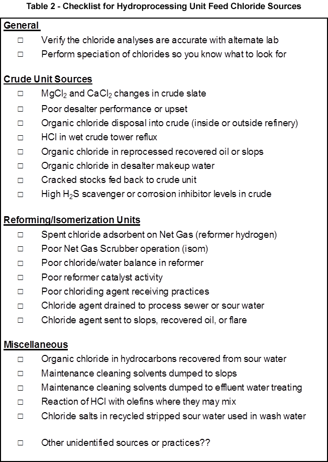
You can systematically work your way through the list. Be sure to actually consider and prove or disprove each possible source. From experience, most locations that have had a problem that they thought was from an outside source, actually had internal problems they did not recognize. Do not make assumptions and eliminate sources too quickly or without proof. Be sure you understand the actual practices being used in handling any chloride chemicals, not just what the refinery has on paper. Verify procedure vs. practice.
The third article of this series discusses how to manage the chlorides.
If you would like to submit an Information Request please click below: