Rigging Points Of Attachment – A Critical Element of Heavy Lift
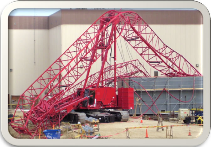
Review of rigging attachments to the equipment being lifted have prevented lift failures. When planning major crane lifts we are very careful about confirming the crane foundation, rigging stability/capacity, and crane capacity. Are we taking enough time to analyze the points of attachment for the rigging? Becht Engineering Heavy Lift Division says “NO”. Our experience is that reviews of rigging points of attachment have identified critical flaws that may have resulted in dropped loads.
In industry today, the load/vessel designers typically design the lifting lugs and trunnions at the same time. It is our experience that the owners of the equipment and the crane contractors are assuming these devices are properly designed and rated. It is a common practice that the crane contractor assumes responsibility for rigging above the points of attachment.
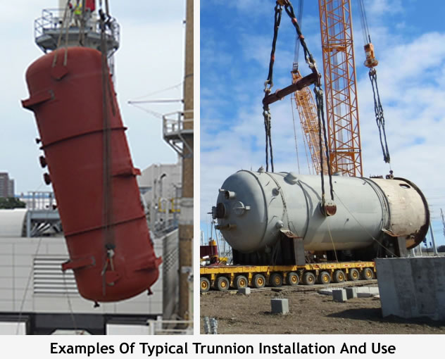
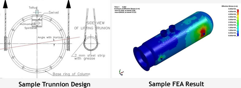
Generally, the consensus is that trunnions and lift lugs are designed by others and they should be right. That has not been our experience. Becht performs a thorough analysis of the points of attachment as part of our engineered lift plan reviews. Our team reviews the design calculations to include the device and the structure it is mounted on, such as a vessel shell or skirt. In addition, we run a finite element analysis (FEA) model to confirm the stresses are with an allowable range.
Considerations for New Equipment
 Confirm the points of attachment are designed and tested according to the ASME BTH-1
- The trunnions must be mounted 180 degrees to each other and leveled horizontally before the lift begins
- Confirm the tailing lug(s) are orientated in proper alignment with the upper lifting trunnion or lifting lugs
- Confirm the D/d ratio of the sling to the trunnions is sufficient
- If using lifting link plates, confirm the diameter of the link plate matches the diameter of the trunnion
- Make sure the trunnion is properly lubricated to minimize friction as the sling or link plate rotates during up ending of a load (Teflon type padding works very well for this)
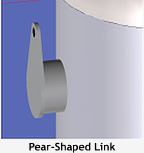
- During the lift, assure the slings don’t get slack at any point during the lift (this sounds like a no brainer but when lowering a tower onto anchor bolts it sometimes gets stuck. The crew and operator may not notice this and the slings can become dislodged or unhooked from the trunnion!!!) This risk can be eliminated by designing trunnions that have a secure connection. This can be achieved with a pear-shaped link, mounted on the trunnion, that can rotate as the load is upended.
Becht Heavy Lift Reviews Disclose Issues
Becht reviews have disclosed numerous issues with trunnions, lifting lugs and the loads they are attached to. One such issue was where the pipe used for the trunnion hub, was overstressed. According to our FEA the pipe would have severely deformed, possibly causing damage to the rigging gear. Becht engineers designed stiffener brackets that were installed inside the trunnion hub resolving the issue.
In another case, when lift link plates were used, the diameter of the link plate was smaller than the diameter of the trunnion. This resulted in point loading of the link plates that they were not designed for. Both diameters matched on the lift plan drawings but the lift contractor did not physically measure to confirm. When the lift started, there was a loud popping sound and the lift was stopped. Fortunately, the problem did not result in a load drop but could have been catastrophic.
Don’t Assume Anything!! Check, Re-Check And Check Again
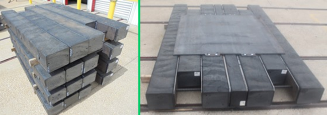
Structural problems with a load or vessel are often encountered. Especially when upending a very long load. In one case, Becht discovered the tower skirt would have deformed due to the stresses imposed by the tailing lugs. Becht made a recommendation to install stiffener beams inside the skirt to prevent any deformation. The beams are shown in the photo below.

Considerations for Demolition Equipment
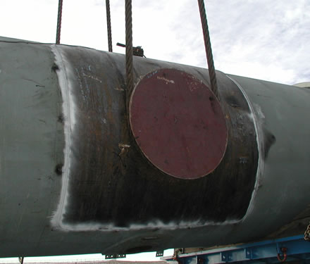
Special consideration should be given to demolition lifts. A thorough investigation must be done to assure the material you are mounting the device to is not overstressed. The integrity of the material should be confirmed. Occasionally we find the vessel shell is overstressed due to deterioration or thinning. In that case, adding a re-pad plate is a common solution. Another solution may include inserting a lifting pipe or beam though the vessel with stiffeners or re-pad plates attached to the shell.
Lifting Lugs
Lifting Lugs require similar checks as trunnions. The main difference is that they must be designed and installed considering specific loading angles. The lug could see a transverse force at the start of the lift, an oblique force as the load is upended followed by an axial force when the load is vertical. Lateral loading is unacceptable but must be considered as an impact factor.
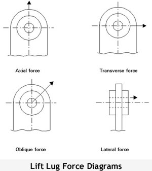
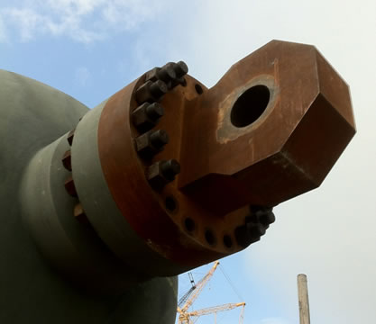
The same codes apply to lifting lugs as for trunnions. See ASME BTH-1 and ASME B30.20.The 1,500-ton lifting lug in the photo below had to be tested to 1,800 tons. ASME allows these devices to be rated at 80% of the test load.
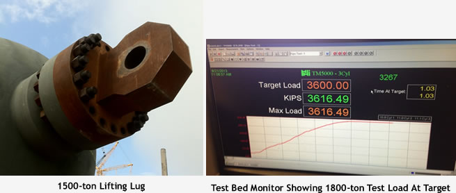
In conclusion, don’t take it for granted that the points of attachment are properly designed to perform to capacity during the lift. The points of attachment may be of sufficient capacity but could damage your load. Take the time to verify the design and assure they meet ASME Code. This blog does not include every consideration but instead is intended to inspire creative thinking and prompt a pro-active approach to design and use of these devices. If you don’t have the engineering skill sets in house, Becht Engineering would be pleased to provide a thorough analysis.
Becht Prevents Problems
Have a question or would like more information? You may post to this blog or click the link below for more help.

 Confirm the points of attachment are designed and tested according to the ASME BTH-1