Computational Fluid Dynamic (CFD) Analysis Resolves Deaerator Cracking
Becht Engineering recently reviewed a utility company’s deaerators which experienced a through-wall, circumferential crack at the toe of the fillet weld attaching the saddle to the shell and a through-wall crack was found at the head-to-shell junction at the steam inlet end of the drum.
 The saddle to shell cracking was attributed to restrained axial thermal expansion of the shell at a tightly bolted sliding saddle support. The crack was ground out, welded and the support modified to permit sliding.
The head to shell crack cause was attributed to corrosion fatigue, a common occurrence in deaerators. The crack was most likely initiated at a weld surface defect on the I.D. of the drum and grew with time. The daily operating cycles of the drum during periods of reduced steam demand and thermal stresses which we attributed to a poorly designed steam inlet nozzle were the main contributors to the crack growth.
A large diameter superheated steam inlet nozzle extended through the head of the drum terminating 18” into the vessel. The steam exited through a rectangular shaped slot opening on the underside of the pipe which directed the flow of superheated steam directly into the condensate on the bottom of the drum near the shell-to-head weld.
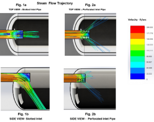
Becht’s computational fluid dynamics model (CFD) indicated that there was little dispersion of the steam exiting the nozzle and that the velocity of the steam mixing with the condensate was relatively high. The superheated steam contact with the cooler condensate resulted in a violent reaction with localized heating and cooling of the vessel shell. This cycling can cause thermal stresses which can result fatigue cracking. Generally, fatigue cracking occurs at welds and heat affected zones adjacent to the weld. Notably no such weld cracking occurred at the opposite end drum where there is no steam inlet nozzle. Figures 1a and 1b demonstrate that the flow trajectory of the incoming steam acts more like a high velocity jet of steam directed at the condensate in the bottom of the drum.
To provide better dispersion, Becht recommended that the inlet pipe be modified with multiple and wider distributed holes. In this configuration, the nozzle acts as a sparger which better disperses the steam in all directions and at lower velocities as can be seen in Figures 2a and 2b.
Contact