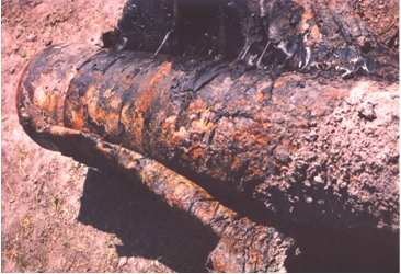
Predicting the Remaining Life of Corroded Buried Pipes

When planning or performing a wall thickness inspection of buried pipe, it is necessary to establish the procedure to be used in evaluating the thickness readings, and determine the pipe’s fitness-for-service (FFS), which will be the basis of run-or-repair decisions.
We are currently working with EPRI to develop such a procedure. This article is intended to provide a broad brush of the FFS process for buried pipe.
An industry that has come to grips with this process for over 30 years is the oil and gas pipeline industry. They use ASME B31G to assess the integrity of corroded pipelines. The ASME B31G procedure is simple, conservative, and … not applicable to nuclear plant buried pipes. The reason is that B31G contains assumptions regarding the operating loads, the operating pressure stress, and the equivalency to a hydrotest which are not applicable to ASME B31.1 or ASME III lines.
Another reference would be ASME XI Code Case N-597 and API 579 / ASME FFS-1, for safety-related and non-safety related pipes respectively. But neither document explicitly addresses buried pipes.
To tackle the question of buried pipe, a few years back we formed a joint ASME-ASCE Task Group, and we compiled the key design formulas in a single document, which can be found at www.americanlifelinesalliance.org. This document is quite useful in re-generating the design calculation and hence the design margin of a buried pipe, a pre-requisite to the evaluation of the corroded condition. Another useful reference is NUREG-CR-6876.
The first step in the fitness-for-service assessment of buried pipe is to assemble the piping and trench design and as-built data.
The second step is to compile the operating and design loads: internal pressure (including water hammer if credible), soil and surface loads, hydrostatic pressure from water table, ground settlement if any, constrained thermal expansion-contraction, frost heave if applicable, seismic wave passage and seismic anchor movements, etc.
The third step is to calculate the minimum wall required to sustain the operating and design loads in accordance with the design code.
The fourth step is to compile the measured wall thickness, in the form of a corrosion map (topography of corroded region, C-scan). The inspection results are trended to determine the future corrosion allowance (FCA) which is the projection of future metal loss until the next inspection or repair.
The fifth step is to assess the effect of wall thinning on the design margin for internal pressure loads. This can be done in accordance with the design code, ASME XI CC N-597 and API 579 / ASME FFS-1.
The sixth step is to assess the effect of wall thinning on the design margins for the other operating and design loads.
The seventh step is to assess the adequacy of the margins calculated in the fifth and sixth step, and on the basis of these results establish the date of the follow-up inspection or the need and date for repair or rehabilitation.


