Real Examples of Chemical Decontamination Success in Refinery Turnarounds

Welcome to Part Four of Becht’s four-part series on chemical decontamination in refinery turnarounds. Our teams have seen firsthand how effective planning and the right chemistry make a measurable impact on turnaround performance. This series shares practical insights from real projects and highlight approaches to help refineries achieve safer, more efficient shutdowns. Read Part One here, Part Two here, and Part Three here.
Here are some actual examples of chemical decontamination applications that I have been fortunate to be involved in. By illustrating how effective chemistry and planning can translate into safer, faster refinery turnarounds, I hope these projects will provide food for thought as you consider your own scope.
Crude distillation unit
There are several distinct areas of application within a crude distillation unit that can save significant time on the turnaround.
Preheat exchangers
Many refineries now wash the entire crude preheat exchanger train with a decontamination solution prior to opening for extraction and high-pressure water jetting. This can make the bundles easier to pull while releasing little or no hydrocarbons into the work area. It can also significantly reduce the time required to jet the bundles at the wash bay, minimizing the risk of a “log jam” at the bay (i.e., bundles get turned around faster).
If certain bundles are not due to be inspected, it is possible to remove the need for extraction, leave the exchangers intact, and start back up without any mechanical work. This saves time and a huge amount of cost. Resulting furnace inlet temperatures at start-up have been reportedly close to those of the jetted bundles. Even if only the exchangers that foul most severely are targeted for chemical decontamination, meaningful benefits can still be achieved. However, it is essential that the desalter is bypassed when washing the entire preheat train to avoid adding a very large volume to the circuit and displacing solids from the desalter into the downstream exchangers.
Desalters
For many years, refineries cleaned their desalters at turnarounds by putting people inside to literally dig out the sludge left after draining down the desalter. Even with the help of vacuum equipment, this typically took one to two weeks of dangerous, difficult work in confined conditions. The volume of sludge removed from a large desalter could be over 100 tons, but ironically, a large proportion of that sludge would be hydrocarbon-binding inorganic solids.
Thankfully, more and more refineries now clean their desalters using chemical decontamination techniques, slashing the time needed to prepare the desalter for opening (and inspection) and removing the need to put in a cleaning crew. Desalters are not designed to drain very efficiently, but if there are solids left behind once the vessel is opened, they will be inorganic in nature and not create a hazardous atmosphere. These solids can usually be washed away with a hose!
Two successful techniques I have experienced are:
- Full circulation (upflow): A totally full desalter is circulated in an upflow configuration, using as many tie-in points as possible at the bottom of the desalter (including the inlet distribution header, the mud header, and the effluent header). A hot (176–194°F or 80–90°C) decontamination chemical solution is circulated for 8–12 hours before draining away, followed by a rinse with clean water.
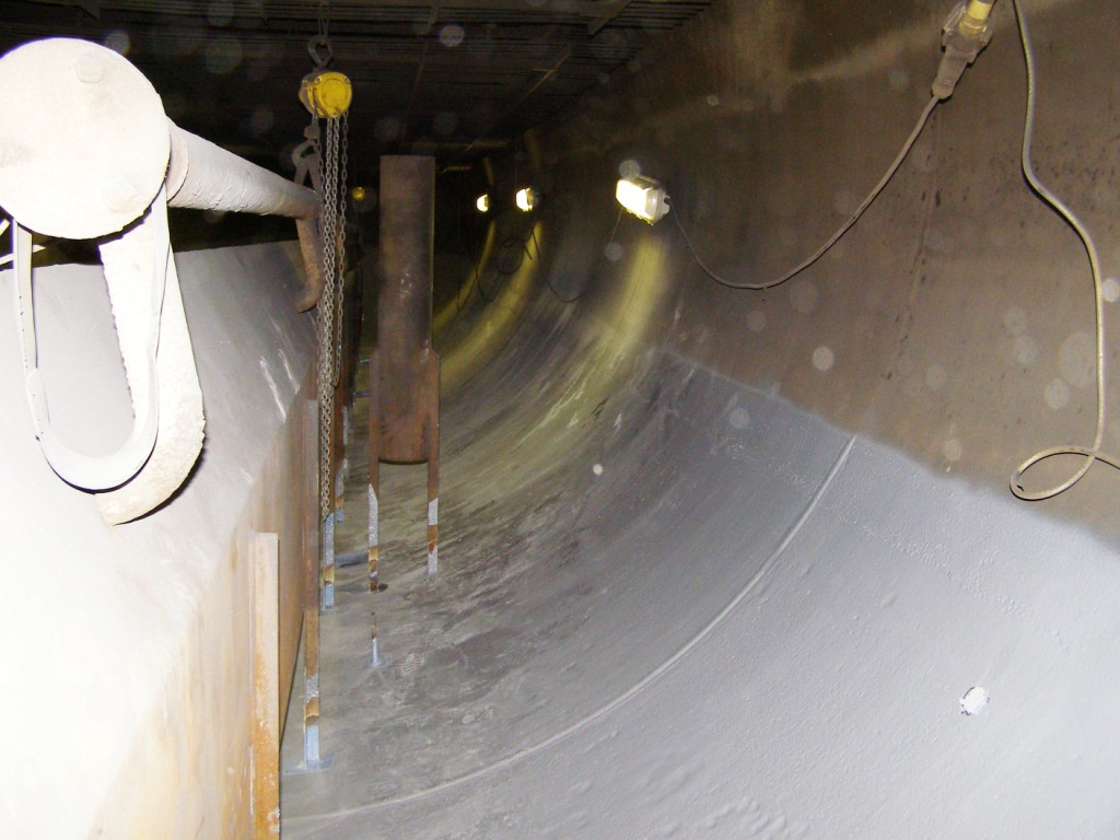
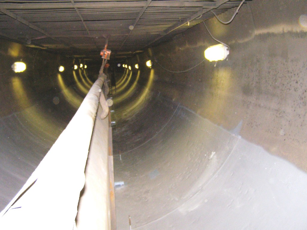
Figure 1: Post-decontamination internals
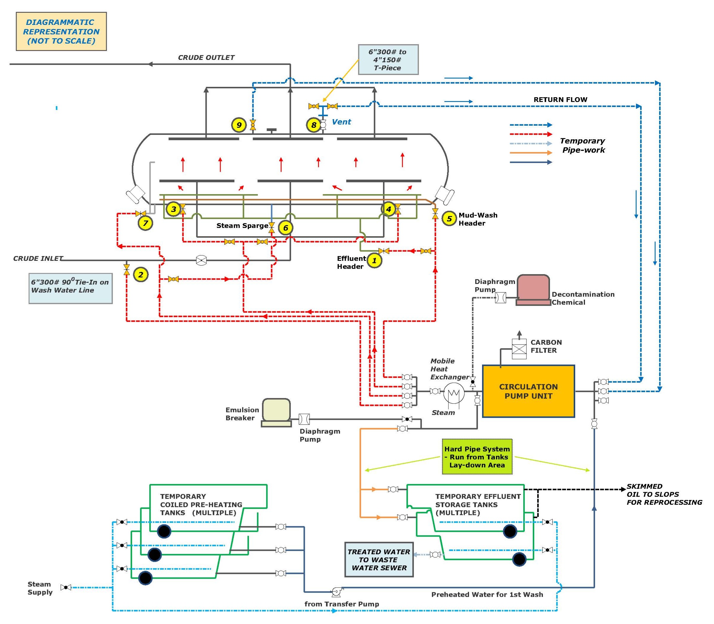
Figure 2: Schematic of temporary system
- Boil-out and vapor phase: A desalter is filled about 50% with decontamination solution and steam is injected via the integral header of the desalter. The solution is then boiled to create agitation and solubilization of the hydrocarbons in the sludge, also known as a “rumble.” At the same time, vapor-phase chemical is injected into the space above the boil-out solution to clean the upper section of the desalter, particularly the grids.
Both techniques have provided excellent results in less than 48 hours, inclusive of filling and draining times and of any final hosing-out of harmless solids. That is a time savings of at least a week compared to man-entry, complemented by a huge improvement in safety.
Vacuum distillation column
It is frequently sufficient to vapor phase the atmospheric column, but the vacuum column often requires a more focused approach. This can be because of heavier hydrocarbon deposits, especially in the lower half of the column, and the possible presence of pyrophoric FeS. The issues can be complicated by chimney trays (especially in older columns) and packed sections. As a result, I have used a number of techniques depending on the column design and past turnaround experience of the client.
- Full cascade wash: A cascade of the entire column, top to bottom, using a hot chemical solution, followed by an oxidizer solution to neutralize any remaining pyrophoric FeS or pockets of H2S. The design of the column and tray or packing arrangement will probably require multiple tie-in points to ensure uniform contact and to get around chimney trays
- Partial cascade wash with vapor phase: A cascade wash of the bottom of the column (how far up or down the column will depend on the design) using a hot chemical solution, while vapor- phase decontaminating the upper section of the column
Depending on the level of contamination, these techniques can take 12-36 hours to provide a completely gas-free, H2S- and FeS-free, clean vacuum column, ready for maintenance work.
- Heavy or waxy crudes: Where the crude unit is processing heavy or very waxy crudes, it is also possible to save time by using a specific decontamination chemistry designed to be applied with a hydrocarbon carrier, such as Light Cycle Oil (LCO) from the FCCU or gas oil (diesel). A mixture of this type of chemical in LCO has been highly successful in removing very heavy deposits from the vacuum column bottoms and vacuum residue exchangers.
Flare gas knockout drums
Flare gas knockout drums, whether located in the process area or offsite, are highly hazardous pieces of equipment to open and require thorough chemical decontamination before even considering opening a manway or inspection hatch. Typically, there will be solids (sludge) accumulated in the bottom of the drum, and those solids will contain both H2S and pyrophoric FeS. Therefore, disturbing that sludge will release H2S immediately – and at very dangerous levels.
The safest approach is to thoroughly decontaminate the drum before opening to atmosphere. Chemical cleaning is made more difficult by the presence of weirs and baffles, depending on the duty and the design, and it is essential to identify tie-in points that can be isolated while temporary piping connections are made. It is highly desirable to ensure that the flow of decontamination chemistry is directed to either side of any weir or baffle, to avoid leaving a buildup of solids on one side of the foot of the weir. That could harbor H2S and pyrophoric FeS, which will be dangerous when the drum is opened, having been assumed to be clean.
Most chemical cleaning contractors will perform two hot chemical washes, reversing the flow to either side of the weir or baffle to avoid the issue described above; they will then rinse the drum with an oxidizing solution such as Sodium Percarbonate, which can be monitored as small incremental additions are made until a positive excess of oxidizer is maintained for at least 20 minutes. That ensures all sulfides have been neutralized. I have seen this technique work very successfully for many years, with several companies.
This approach not only provides a higher level of safety for the workforce, but also avoids unnecessary delays when a contaminated drum is opened and creates a hazardous area that impacts other work, too.
Reformers
Polycyclic Aromatic Hydrocarbons (or PAHs) are sometimes found in methane reformers. These compounds can form inside the reformer tubes and may be carried with the product stream, potentially leading to fouling or catalyst deactivation and carrying significant occupational health risks during maintenance. They are known carcinogens and when I first started talking to refineries about PAHs in their reformers, the sludge that was often present when equipment was opened was colloquially referred to as the “Red Death.” It sounds a bit excessive today – and possibly litigious – but that is how dangerous it was considered by some refiners.
Fortunately, being aromatic hydrocarbons, they can be washed from the reformer stabilizer equipment using appropriate decontamination chemicals – especially terpene-based formulations, which seem to be very effective at penetrating and dispersing any sludge deposits. Contractors will typically conduct two washes, possibly with a rinse in between each wash stage, and may follow up with an oxidation rinse depending on their preferred procedure. Whichever approach is used, it is essential that the closed-loop circulation is designed very thoroughly to ensure that no dead legs or pockets of solution are left in the reformer circuit. Multiple tie-in points should be identified, as a simple “one-in, one-out” loop is unlikely to provide adequate contact with contaminated surfaces.
The aim here is to eliminate, as far as possible, the exposure to highly dangerous compounds, and avoid incurring delays if a section of the reforming process area is suddenly barriered off while extra cleaning is done.
FCCUs
On most fluid catalytic cracking units (FCCUs), the main fractionator presents the biggest chemical decontamination challenge: making it safe for entry and maintenance/inspection work within a reasonable timeframe. Previous pyrophoric incidents have led some refineries to completely flood their main fractionators with water during cleaning and gradually lower the water level as cleaning crews removed deposits from one tray at a time. This is a slow and hazardous process requiring personnel to wear breathing apparatus and significantly impacting productivity.
It is entirely possible to chemically decontaminate a Main Fractionator to the extent that it can open gas-free and pyrophoric FeS free, allowing rapid access for maintenance personnel. Typically, if applying a washing technique, two consecutive applications of chemical solution will be required for optimum cleanliness, and an oxidiser rinse to ensure all pyrophoric FeS has been completely neutralised. It may also be possible on some Fractionators to achieve good results with a combination of washing and Vapour Phase chemistries. For certain, there is no longer a need to fully flood such large columns with water to combat possible pyrophoric issues.
In one instance I am aware of, a European refinery completely filled their main fractionator at every turnaround and slowly drained each section as internal inspection work progressed from the top tray downward. This took up to a week before any maintenance work could start. The refinery decided to apply a cascade wash approach with a proven decontamination chemical followed by an oxidizer rinse using the same cascade technique – all of which was completed in 36 hours. The fractionator opened gas-free, H2S-free, and at zero LEL. Maintenance crews entered within hours of the decontamination finishing. This saved the refinery five days compared to the previous turnaround.
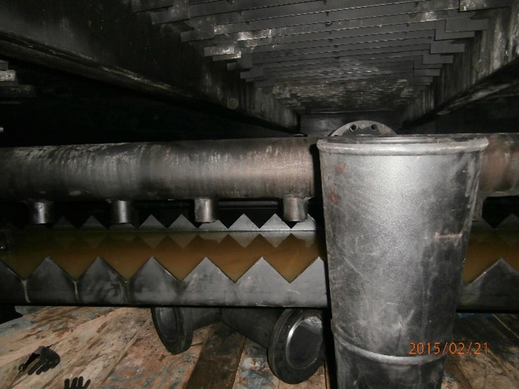
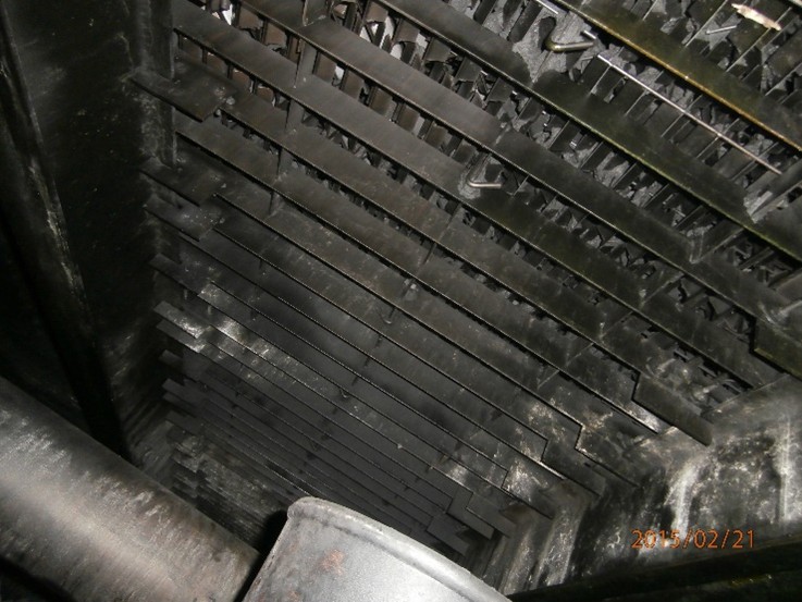
Figure 3: Main fractionator – bottom bed
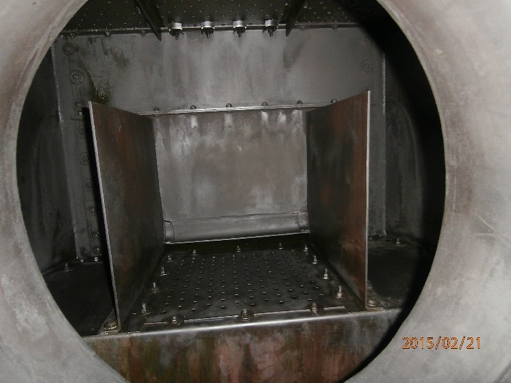
Figure 4: HCO side-stripper
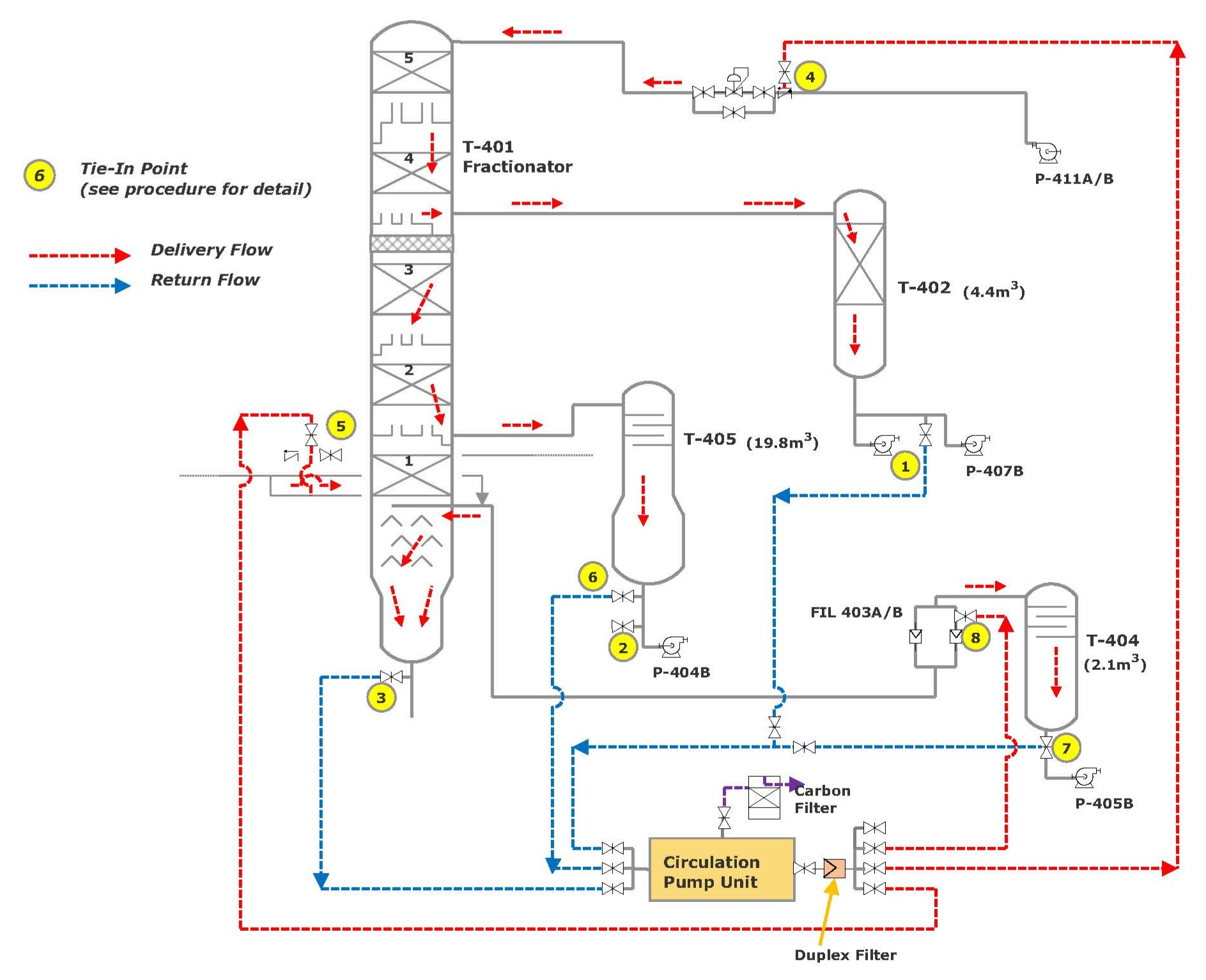
Figure 5: Circulation schematic of main fractionator and side-strippers
Another area of the FCCU that deserves special focus is the slurry loop on the bottom of the main fractionator. These critical exchangers are frequently fouled with significant quantities of catalyst fines and coke. When the exchanger bundles are extracted, they require substantial time at the wash bay to remove the fouling. However, chemically decontaminating the exchangers in-situ as part of the overall main fractionator procedure can make the bundles easier to extract, minimize contamination in the area around the fractionator base, and significantly reduce water-jetting time at the wash bay.
In the worst fouling cases, it can be beneficial to wash the bottom of the main fractionator and slurry exchangers as a discreet loop or closed circuit, before decontaminating the rest of the fractionator. This also removes the risk of taking solids from the bottom of the fractionator and distributing them from the top down, contaminating comparatively clean trays and/or packed sections. In-line filtration can of course minimize this, but the temporary filters tend to block rapidly and require constant attention.
As mentioned earlier, there are particular hydrocarbon/solvent-based chemicals available for heavy vacuum column bottoms that are very effective at mobilizing the slurry solids and removing the bulk of the fouling. The decontamination chemical is preferably mixed with LCO and circulated at around 194°F (90oC) for up to 12 hours through the bottom of the fractionator and the exchangers. (Some contractors may specify longer or shorter circulation.) The spent solution is pumped away before the main circulation wash commences.
Summary
I hope these examples have provided useful insights and practical ideas for your next turnaround. I am sure much of this will be familiar to refineries that have been practicing chemical decontamination for many years, but my goal has been to provide a measure of guidance for preparing and executing decontamination work, incorporating it into the overall turnaround plan, and selecting the best contractor and chemistry for the scope – all with safety and time savings as the key objectives.
If you would like to discuss how Becht can help you plan or optimize chemical decontamination during your next turnaround, contact us anytime to start the conversation.
Like what you just read? Join our email list for more expert insights and industry updates.