An Integrated Approach to Limit the Effects of Water Hammer on Piping Systems
This article describes an integrated study of thermal-hydraulic and structural loading of bounding piping systems, to establish an operating envelope, screening criteria, and rules of good design practice to protect piping systems from damage caused by valve closure water hammer.
Introduction
In many cases of operation or flushing of piping system, it is necessary to close a valve on an established flow. The fast closure of valves in a piping system has the potential to cause a water hammer in the piping system. A study was conducted to determine the operating envelope and piping characteristics that would limit the water hammer-induced occasional stresses and pressures to be within the ASME B31 limits. The investigation of such transients involves the prediction of the transient hydraulic loads and the evaluation of the piping system response to the predicted loads.
Screening Criteria
Based on experience with prior analyses of several typical routes, and a review of all configurations, the study selected bounding piping layouts and configurations, most susceptible to overload from a postulated water hammer event. The following screening criteria were determined to be significant in selecting bounding layouts and configurations for the leak check studies:
- Piping runs with long spans between supports
- Piping with concentrated weights with limited supports
- Routes where water hammer loads are unbalanced
- Pipes with area changes, which cause reflected waves that amplify system response
- Unbalanced force at unrestrained free ends such as hose attachments
- Fittings or connections with loss coefficients
- Various distances from the water supply source to maximize rebound loads
- Routes with weak pipe supports such as cantilevered angle iron
Hydraulic Loads
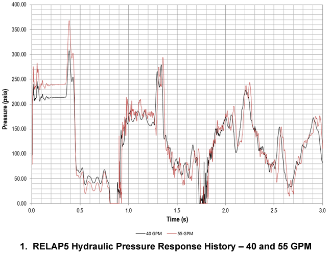
Bounding cases were developed to maximize loads on the piping and structural supports. The bounding cases were selected considering the above screening criteria. The time-dependent transient water hammer pressures were then developed using the RELAP5© hydraulic code. An example of pressure loading at flow rates of 55 and 40 gallons per minute (gpm) is shown in Figure 1. The pressure profiles, the peak pressures, and the durations between peaks of pressure are as would be expected.
Mechanical and Structural Response
The pressure transients have two major effects on a piping system: (a) An over-pressure (hoop stress and pressure rating) effect, and (b) A beam (longitudinal stress) effect.
The assessment of the hoop effect is classic, and consists in (1) evaluating the over-pressure against the allowances in the B31 code, (2) addressing the pressure rating of joints and components, and (3) addressing the hoop stresses in the piping, fittings, and components.
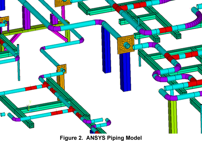
The evaluation of the beam effects (longitudinal stress effect) is performed by time-history analysis. The transient loading from the RELAP5© hydraulic model at different flow rates is applied to the structural model of the piping system to determine the resulting forces, moments and stresses acting on the system, using the ANSYS® finite element analysis program. The structural models use a combination of pipes, beams, shells, and spring/contact elements to represent the piping configurations. A piping section is shown in Figure 2. The model accounts for stress intensification factors, flexibility factors, valves, tees, reducers, and elbows. The pipe flexibility factors and stress intensification factors are implemented into the ANSYS® piping model for the elbows and tees, based on the ASME B31 Code. The piping models are evaluated for water hammer and concurrent loads.
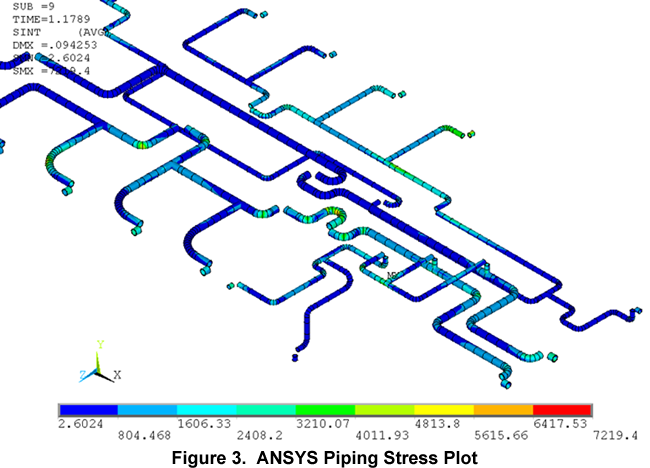
The piping and pipe support member stresses for each flow rate are evaluated to determine if the code limits for occasional loads are met. A stress intensity plot of the piping is shown in Figure 3. If any element of the piping system does not meet the criteria, a reduced flow rate is imposed and evaluated. This process is followed until all elements of the modeled piping system meet the occasional load limits. This approach is repeated for a broad sample of piping systems. The flow rate and pressure are then set so that all evaluated models meet the B31 Code occasional stress limits.
The study provides a basis to set limits on operating and flush flow rates and pressures that would permit the operator to close valves without causing water hammer damage to the piping systems.
Practical Design Considerations
The water hammer evaluations of the integrated piping-support network reveals that in general, the piping is better able to accommodate the water hammer loading than the pipe supports. The supports, in particular the member welds in the supports, are normally the weak link of the piping network. The controlling elements are the attachment welds between the pipe and support, welds between individual structural members, U-bolts, and anchor bolts. This conclusion is in line with classic damage from water hammer.
The study identified the weakest elements of each piping anchor group because all components were evaluated together. The piping anchor groups reviewed in the study shared similar design details that were consistently identified as the weak links. In light of this understanding, it is possible to implement rules of good practice for future designs. Implementation of the rules of good practice will increase design margins resulting in more robust piping systems with improved resistance to water hammer.
Conclusion
This article described an integrated study of thermal-hydraulic and structural loading of piping systems that was conducted to establish an operating envelope to protect the piping systems from overloads from valve closure water hammer. The use of bounding piping configurations and the limits on flow rate and pressure permit operations to proceed without additional limitations and will minimize future route-specific water hammer analyses. Another benefit of the study is the identification of weak links in piping route designs and the establishment of rules of good design practice that can be applied to future modifications.
Have a question or would like more information? You may post to this blog or click the link below for more help.
[readon2 url=”index.php?option=com_rsform&view=rsform&formId=4&Itemid=739&lang=en”]Request Info[/readon2]


