Hydroprocessing Relief Issues – Chapter 2 – Separator Blow-Through
This is the 2nd of 3 articles discussing relief issues for Hydroprocessing units. Last month, we discussed backflow prevention (CLICK HERE for 1st article). As a reminder, the three main lessons from that article are:
- Backflow protection must be provided on low-pressure to high-pressure interfaces including feed streams, wash water streams, and lean amine streams flowing to the high-pressure section of the recycle loop.
- Check valves are not adequate by themselves for backflow prevention in hydroprocessing units
- Additional layers of protection are often provided by:
- Adding a chopper valve that shuts on low flow
- Having a relief valve on the low-pressure system capable of relieving the full backflow
Next month, Chapter 3 of this series on relief protection, will discuss blow-through from low-pressure separators to distillation columns. As a reminder, these topics will be the subject of an AFPM Safety Bulletin to be released in 2Q, 2023.
Overpressure on Separator Systems
Separators are an important part of the high-pressure recycle loop. High-pressure separators are used to flash off gas from the reactor effluent and to separate liquid water from liquid oil. Most units employ a low-pressure separator to flash off hydrogen gases that are dissolved in the oil coming from the high-pressure separator. Proper use of a low-pressure separator removes most non-condensable gases and makes the distillation column smaller.
There are a variety of separator systems used in hydrocrackers and hydrotreaters. Some units have hot separator systems, but almost all units have low-pressure separator(s). For the small minority of units that do not have a low-pressure separator, this discussion still applies for the distillation column that is downstream of the high-pressure separator.
The ratio of pressure between the high-pressure separator(s) and the adjacent low-pressure separator(s) is often high enough to potentially cause significant overpressure in the low-pressure separator. The table below shows various levels of overpressure that cause concern:
Overpressure Consequences

Reference: API RP 581 Risk-Based Inspection Methodology, Table 6.14
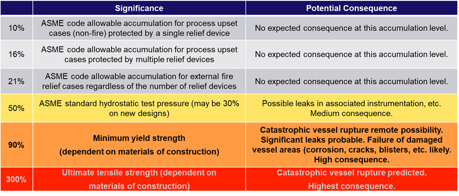
This table shows that catastrophic vessel rupture is likely at 300% overpressure. Hydroprocessing units often have a high-pressure loop operating at pressures exceeding 2500 psig or more with feed or washsystems with design pressures less than300 psig resulting in a potential overpressure of 1000%.
Industry-Defining Incident: Separator Vapor Blow-Through
At about 7am on the morning of March 22, 1987, the day-shift operators were assembled in the control room of the hydrocracker at a refinery in Scotland to start their shift. The crew was planning to finish starting up the hydrocracker.
The high-pressure recycle loop was fully pressured and the separator had oil in it. During the night, the separator level control valve had been manually opened to flow oil out of the separator to keep the line from setting up with waxy product.
Shortly after the start of shift, the level control valve on the high-pressure separator was opened again to keep the line warm. During this operation of the level control valve, the oil drained out of the separator causing high-pressure hydrogen gas to flow to the low-pressure separator. The relief valve on the low-pressure separator was sized for a fire case, but not for gas blow-through.
Within seconds, the low-pressure separator ruptured. A crane driver who happened to be walking past the low-pressure separator was killed, but no other injuries occurred. The blast was heard up to 20 miles away. Pieces of the low-pressure separator weighing up to 3 tons were scattered over a half mile away.
Rebuilding the unit took over 18 months and a cost of over $100MM.
The picture below comes from the government incident report. You can see the support saddles for the low-pressure separator in the lower, middle portion of the photograph.
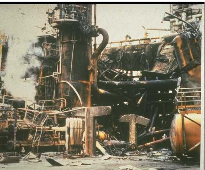
Link to the incident report: Hydrocracker Explosion and Fire at BP Oil, Grangemouth Refinery (hse.gov.uk)
Lesson: Among other cases, the relief valves on a low-pressure separator must be designed for vapor blow-through.
Key Factors for Vapor Blow-Through
- Vapor blow-through leads to large relief requirements with important design details on liquid inventory, vaporization, etc.
- The main barrier for vapor blow-through during operation is a liquid level in the high-pressure separator
- Vapor blow-through is caused by loss of the liquid seal on the bottom of the vessel
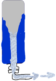
- Once vapor blow-through starts, it can cause liquid coming into the separator to “stack up” on the walls of the vessel making it impossible to stop vapor blow-through without closing the level control valve on the high-pressure separator (see sketch below).
Design Considerations for Vapor Blow-through from High-Pressure Separator
- Review EACH high-pressure liquid level valve and bypass as a source of overpressure (e.g., separators, amine, sour water, knock outs, etc.). If it is possible for a valve or bypass to be open during normal operation, then the flow contribution from that flow path must be considered as part of the required relief load.
- For each source, assume all automated valves are simultaneously open unless they are “locked out” of operation. Some units such as two-stage hydrocrackers have multiple high-pressure separators that flow into a common low-pressure separator. It is common to assume that only one high-pressure will suffer vapor blow-through at a time.
- Manual valves should be assumed to be wide open.
- Power recovery turbines will only provide limited resistance to vapor flow and this flow should be considered as part of the downstream relief load.
- If a restriction orifice is sized to limit the flow, verify that the plate thickness is designed considering maximum pressure drop.
- Assume 100% vapor blow-through with no credits for liquid reducing flow. This case can happen during shutdown and startup as illustrated in the BP Grangemouth Incident.
- The low-pressure separator must be able to hold the liquid surge that may precede vapor blow-through from the high-pressure separator. If the low-pressure separator fills up or carries over liquid into the relief valve, the relief valve may be incapable of the required load. The worst-case scenario is where the liquid surge fills up the low-pressure separator followed by vapor blow-through. The effect of the vapor blow-through will cause the liquid to act like a “piston” through the relief valve – meaning that the relief valve must pass liquid at the rate the vapor blows through from the high-pressure separator. It’s very unlikely that the low-pressure separator relief valve will have this capability.
Why is a Low-Level Chopper Valve on the High-Pressure Separator Oil Outlet a Very Bad Idea?
Since we have established that vapor blow-through should be avoided whenever possible, why not stop vapor blow-through with a chopper valve on the high-pressure separator oil outlet activated by a low liquid level? The intent of all safety interlock systems (SIS) should be that they solve more problems than they create. In this case, a low-level chopper valve will cause more problems than it solves.
The main reason a chopper valve is a bad idea is this will cause the high-pressure separator to fill up quickly leading to:
- Loss of the recycle compressor on a high-level shutdown at the separator or downstream knockout pot. Loss of the recycle compressor is a major upset event in most hydroprocessing units. Recycle loss is one of the major causes of reactor runaway events.
- Pressure increases in the recycle loop eventually causing the relief valve to open leading to two-phase flow to the relief system. Two-phase flow into the relief system from the high-pressure relief valve(s) will lead to loss of containment and a profoundly serious incident. There have been multiple incidents in relief systems due to two-phase or liquid flow in the vapor relief system. Consider the following incident:
Relief Piping Rupture due to Liquid Flow to Vapor Relief
A hydrocracking unit suffered a leak in the sour water piping coming out of the high-pressure separator. Rather than shutdown the unit to repair the leak, a convenient routing was found to put the sour water into the vapor relief system. Sour water was pumped from the relief drum to the sour water tank so the unit could continue to run while the leaking piping could be repaired.
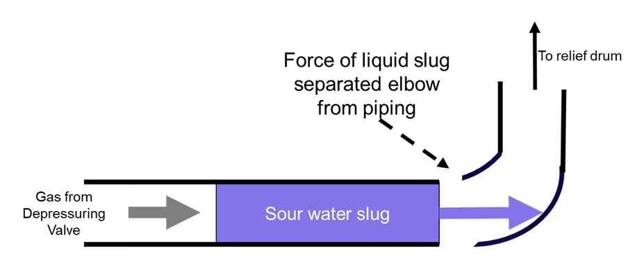
A short time later, the unit suffered a major upset causing a reactor runaway. Per emergency procedures, the emergency depressuring valve was opened to mitigate the runaway. The high velocity of the hydrogen flowing into the vapor relief system caused the sour water to form “slugs” that were accelerated to a high velocity. One of the sour water slugs hit a piping elbow on the relief line with enough force to separate the elbow from the piping. The sketch below illustrates the piping rupture incident.
Fortunately, the unit was successfully shutdown while mitigating the runaway without injury and without a fire from the piping rupture, but this incident easily could have resulted in a major fire.
This incident shows the problem with liquid flow or two-phase flow to relief: the piping is just not designed to manage the momentum of the liquid slugs that can form and destroy the relief piping, especially with the velocity and force created by vapor released from the high-pressure loop.
Summary of lessons for vapor blow-through from high-pressure separators to low-pressure separators
- Relief valves on low-pressure separators must be designed for vapor blow-through
- The design vapor blow-through rate must consider all potentially open level-control valves and bypass valves in the system
- The low-pressure separator must be able to contain the liquid surge from the high-pressure separator without filling up or carrying over liquid into the relief system
- Never use a chopper valve between the high-pressure separator level to prevent blow-through. Closing a chopper valve on the high-pressure separator oil outlet will likely cause a much bigger upset than vapor blow-through and could result in a loss of containment in the vapor relief system.
- Do not allow liquid or two-phase flow into the vapor relief system.
Application in your unit(s)
It is possible that you have not experienced a blow-through incident in your career or in your unit, but one of the purposes of this article is to show what can happen and the dangerous outcomes including personnel injury, fatalities, and devastating plant destruction.
Does your unit or units have adequate blow-through protection on each low-pressure separator? Is the capacity of the relief valve(s) adequate per the design criteria listed in this article? Contact us for all of your hydroprocessing needs.
Special thanks to Wendy Wildenberg of Flint Hills Resources for her assistance on this topic.
Next month, we will discuss blow-through issues from low-pressure separators to distillation columns.

