Correcting Splitline Leaks on Dresser-Rand M-Line Compressors
Two compressors at a refinery in Texas were up-rated to bushing type dry gas seals to eliminate the historical H2S leakage to the environment. The existing seals in both of these machines were the original Clark floating bushing oil seals. There were concerns that the leakage path may be around the outside of the seals at the splitline and not axially through the seals. To assure that the gas seal upgrade was addressing the root cause of the leakage, testing was performed to determine if the case could be leaking around the seals at the splitline. The information below illustrates in detail the tests performed, the results of the test, and the subsequent modifications made to the compressors to reduce the potential for case splitline leakage.
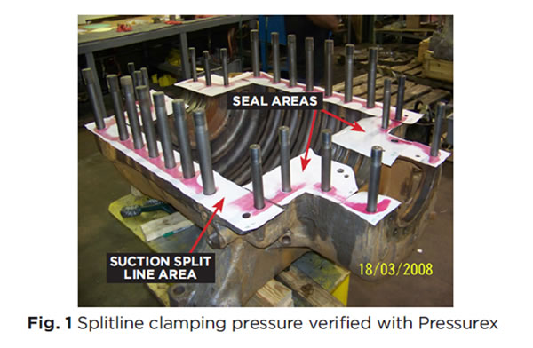
Both Compressors were removed from the Refinery and repaired at the Dresser-Rand (D-R) repair facility in Houston, Texas. Both machines were dissembled and inspected to determine the necessary repair scope. Both of the machines required extensive repair in the diaphragm-to-case fits, inlet guide vanes (IGV)-to-diaphragm, seal and bearing fits. One of the compressors required splitline grinding so all of the associated fits had to be re-machined. Once the case repairs were completed, the case splitline contact was checked. A pressure sensitive paper (Pressurex) was installed covering the bottom half of the case splitline. The Pressurex is a thin, white plastic sheet that turns different shades of red in the contact area depending on the clamping pressure.
The shades of red can be compared to a color chart provided with the Pressurex that relates the shade of red to the clamping pressure. For this application the medium grade Pressurex, was utilized which captures contact pressure between 1,400 PSI to 7,100 PSI. The upper half compressor case was installed on the lower half and the bolting was torque to original equipment manufacturers (OEM) specifications. After thirty minutes the top half was removed and the Pressurex was inspected to determine the condition of the splitline sealing surface and the splitline contact in the sealing area. The test showed there was little, if any clamping pressure in several areas. The seal areas and two other areas on the split line on the suction end indicated that there was less than 1,400 PSI clamping pressure in these areas. (Fig.1)
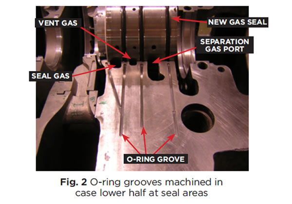
The deficiencies at both the seal and suction area splitline were addressed by machining O-ring grooves in the bottom half of the compressor case. The machinery Owner and the Becht advisor decided on the location and size of the O-rings installed. The seal splitline O-rings grooves were machined close to the inner edge of the seal gas port lands then extending radially outward toward the splitline bolting where acceptable clamping pressure was confirmed by the Pressurex (Fig. 2). This modification will prevent leakage gas from entering the vent gas port, the separation gas ports and the atmosphere on the new dry gas seal installation.
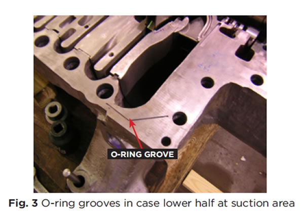
In the area of minimal clamping pressure on the suction end splitline, O-ring grooves were machined in the splitline to prevent internal leakage across the splitline. These grooves were machined from areas of acceptable clamping through areas of minimal clamping then terminating once areas of good clamping pressure were reached. (Fig. 3)
After all the repairs were completed on the compressor cases, the diaphragms and IGVs were adjusted for correct fit and installed. Pressurex was installed on the entire split line to check for acceptable clamping pressure and possible interference with the diaphragms or IVGs at the splitline. (Fig. 4)
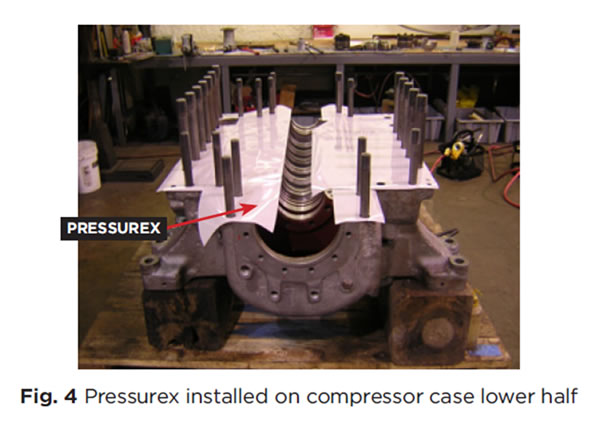
The top half compressor case was installed on the bottom half and the splitline bolting was torqued. After thirty minutes the top half of the compressor case was removed and the Pressurex was inspected.
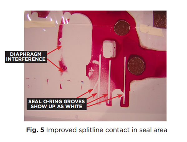
The seal o-ring groves did extend into an area of acceptable clamping force as did the suction end o-ring. The improvement of the splitline contact (Fig. 5) is a result of surface grinding both the top and bottom halves of the compressor case. Notice the red impression to the left of the seal housing where the Pressurex indicated that the bottom half of the first diaphragm had an interference fit to the top half of the first diaphragm. This would have prevented the casings from sealing which would result in a leaking splitline in that area. The diaphragms were modified to insure proper clearance between the top and bottom halves.
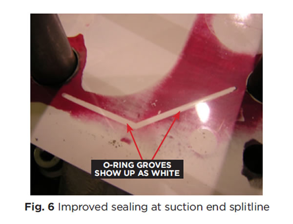
The suction end splitline o-ring groove now had sufficient clamping force on both ends which should prevent leakage in this area. (Fig. 6)
The compressors were reassembled with the new gas seals and returned to the Refinery. The compressors were installed and pressure tested successfully. With the aid of the Pressurex to locate the areas of improper contact and the installation of o-rings in those areas, the splitline leakage was eliminated. The Pressurex indication of interference on the first diaphragms and the correction of this problem avoided a possible leak. These compressors have been operating without any splitline or seal leaks for several years.
To further improve the M-line compressors seal area and splitline sealing, hydraulic case nuts should be installed on all of the case bolts on both ends of the machine. Due to the M-line case design and welded piping on the upper half case, conventional nuts are very difficult, if not impossible to torque to the appropriate value. These nuts are usually tightened with a strike face wrench, which is not a controllable torqueing method, making leakage more probable at the splitline and seal areas. With the case geometry of the M-line compressor, the seal area corner studs separation is excessive relative to the other splitline bolting making the clamping force in these areas non-optimum. (Ref. Fig.1)
This article was written in response to a question from a Machinery Engineer at a Gulf Coast refinery. He had read several of the previous articles in Machinery Chat and he asked for advice on a problem he was having with M-Line compressor splitline leaks.


