Demister Pads—Simple Devices Until They Don’t Work
A demister pad is similar to an air filter except instead of removing dust particles from a stream of air for example, it removes micron-size liquid particles from a liquid/vapor stream often found in many industrial processes. An air filter prevents dust particles from entering downstream equipment; similarly a demister prevents liquid droplets from entering downstream equipment where they may affect operation or cause damage. In general, a duty specification is prepared by the process designer and given to demister vendors to recommend a demister that meets the duty requirements. Or today, knowing the required duty you can select a demister from the vendor’s online catalog. The demister is installed, performs as intended and is never heard about again. On occasion, problems arise as the case in which Bob Fiocco, a Becht Sr. Advisor, provided technical support to a refining client on demister design and selection.
An existing demister installed in a large diameter process tower/separator let liquid droplets in a liquid/vapor stream carry over into a downstream compressor. As the liquid droplets passed through the compressor, the droplets vaporized leaving behind solid deposits on the hot end of the compressor impeller. Over time the deposits built up on the impeller and broke off causing an impeller imbalance and vibration resulting in a shutdown of a critical unit in the process.
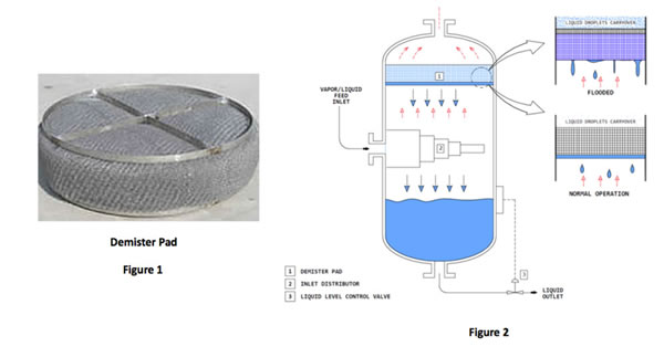
What does a demister pad look like? Demisters come in a variety of shapes and sizes and can be installed horizontally or vertically. A typical horizontal demister resembles a large steel wool mesh pad (Figure 1), several feet in diameter and, 6″ to 12″ inches thick. Fine diameter wires which are typically ~0.011 inches in diameter are interlocked by a weaving operation to form a wire mesh pad with a high free volume (97% to 99+% void fraction) and of uniform density. A “tight” mesh (a lower void fraction and more dense) is more effective, i.e., it captures smaller diameter liquid droplets vs. an “open”, less dense mesh with a greater void fraction.
The principal determinant in the selection of the demister for the issue described herein was flooding. In a typical demister installation (Figure 2), a thin disengaging zone of bubbling liquid (1 or 2 inches in height) develops at the bottom edge of the demister pad. The remaining mesh (active zone above the liquid layer) captures the droplets. The liquid droplets coalesce on the wire mesh and then drain by gravity and accumulate in the disengaging zone, ultimately dripping to the liquid pool in the bottom of the vessel. As the velocity/liquid loading increases, the thin disengaging zone of liquid increases in height moving further into the active zone until carryover of liquid occurs, i.e., the demister is flooded, and liquid is carried over into downstream piping and equipment.
The flooding point of a demister is a function of many variables including demister design, vapor and liquid densities, vapor velocity, liquid loading, and liquid properties such as viscosity and surface tension. Although a simple looking device, a lot of know-how and testing dating back to the 1950’s is embodied in their design.
After working with our client and demister vendors, our recommendation was to use a two-stage demister which increases both capacity (throughput) and effectiveness. The recommended demister is made of a 2 inch high-capacity “open” mesh drainage pad on the bottom to prevent flooding and a more effective 4 inch “tight” co-knit mesh pad on the top.
It optimizes separation efficiency and maintains a safe margin between the operating conditions and flooding point.


