Purpose of the Flange Bolt Rules in ASME VIII and ASME III
The partial objective of the ASME Appendices
ASME VIII Div.1 Appendix 2, and ASME III Div.1 Appendix XI provide “Rules for Bolted Flange Connections” with ring-type gaskets. One of the rules provided applies to the calculation of the minimum required bolt area. In other words, what should be the minimum combined cross-section area of the flange bolts to (a) seal the gasket, while (b) not exceeding the bolt allowable stress?
The two force components Wm1 and Wm2
The rules are intended to provide bolts with sufficient pre-tension to achieve two objectives: (1) Counter a pressure-induced force Wm1 which tends to pry open the flange in operation, and (2) provide a compressive force Wm2 which is needed to seat the gasket during initial assembly of the flange joint.
The at-pressure force Wm1
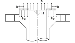
The Wm1 force is in turn comprised of two contributions, illustrated in the Figure: (a) A compressive force H to counter the distributed pressure P imposed on the flange in operation, and (b) a compressive force HP to seal the gasket in operation.
 Wm1 = H + HP
The force H to counter the operating pressure
The force H is simply the internal pressure times the flow area. But, the flow area is not simply p(ID)2/4, where ID is the inner diameter of the flange. Instead, the equation for H assumes that the operating pressure will partially pry open the raised flange face, causing the pressurized area to be wider than ID. The pressure thrust diameter to be used is a diameter “G”, larger than the ID, offset by “b” from the edge of the sealing element, as shown on the Figure, so that:
H= (π G2 /4) x P
The force HP to seal the gasket in operation
The force HP applies to a ring with a width equal to the full gasket sealing width (2b), and a diameter G, therefore a perimeter pG. The formula for HP includes a gasket factor m, which reflects an experimental ratio of the required contact pressure to the contained pressure P.
HP = (π × G × 2b) × P × m
The Sealing Force Wm2
The force Wm2 is the force to be achieved to seal the gasket during flange assembly. It is equal to p.b.G.y, where p.b.G is the area of the gasket, with the same assumption for b and G as in Wm1, and “y” is a gasket-specific minimum design seating stress. The ASME Appendices provide the seating stress y for various types of gaskets. The seating stress “y” can also be obtained from the gasket manufacturer.
Wm2 = (π × b × G) × y
The Bolt Stress
Once Wm1 and Wm2 have been calculated, the larger of the two is divided by the total bolt area to obtain the minimum required bolt cross-sectional area. For ASME B16.5 pipe flanges, at the maximum pressure for the flange class, the B16.5 standard provides a sufficient number of bolts, and sufficiently large bolts, to react Wm1 and Wm2 without exceeding the allowable stress. This check of bolt area to sustain Wm1 and Wm2 is more important for custom flanges, such as those used on vessel nozzles, heads, or manways.
Important Caution
| These formulas in ASME VIII Div.1 Appendix 2, and ASME III Div.1 Appendix XI are meant to check that the bolts have sufficient cross-sectional area. They are not meant to limit the bolt torqueing stress to the allowable stress. Instead, as documented in several studies, and as warned in ASME VIII Div.1 Appendix S and ASME PCC-1, the torqueing stress on the bolt will have to exceed the allowable stress to achieve a good seal. |
Have a question or would like more information? You may post to this blog or click the link below for more help.