Basics of Design By Analysis in ASME Section VIII, Division 2
How hard can it be? I’ve heard from several (unnamed) analysts that because they have access to an FEA program and have successfully applied FEA in other fields, that FEA for pressure vessels should be a snap. What is it about FEA for pressure vessels that makes it unique?
I was recently discussing with another blogger regarding some distinctive aspects of performing Design By Analysis for pressure vessels. We generated several questions, and so I decided to post this in a Question & Answer format.
When do I have to use FEA in my pressure vessel design?
The short answer here is that for most situations, you probably should not be using FEA to design your pressure vessel. The rules for designing pressure vessels in ASME Section VIII, Division 1 and ASME Section VIII, Division 2 have a long history of successful application. So, wherever possible, I would recommend that you follow those rules. However, there are some situations where the rules don’t cover a specific design geometry or load that may necessitate the use of FEA.
In ASME Section VIII, Division 1, that is covered in Article U-2(g), which I have discussed previously. In ASME Section VIII, Division 2, you can move between Part 4 (Design By Rules) and Part 5 (Design By Analysis) a little more easily, subject to the regulations in the locale where the pressure vessel will be located.
What is Design By Analysis?
Design By Analysis, as described in ASME Section VIII, Division 2, Part 5 is a methodical approach for demonstrating the adequacy of a pressure vessel component design. It provides detailed rules for performing analyses. The entire approach of this Code (which has changed substantially from the pre-2007 Editions) is centered on the philosophy of Protection Against Failure Modes. The Code writers (who, by the way are all volunteers) have spelled out four failure modes that require attention:
- Protection Against Plastic Collapse
- Protection Against Local Failure
- Protection Against Failure From Buckling
- Protection Against Failure From Cyclic Loading
- Ratcheting
- Fatigue
For each failure mode, the analyst is presented with multiple options of how to perform the analysis that would demonstrate that the specific failure mode has been protected against. In general, these options involve an elastic method and an elastic-plastic method. For Protection Against Plastic Collapse, the elastic method uses an Allowable Stress Design (ASD) approach, whereas the elastic-plastic method uses a Load and Resistance Factored Design (LRFD) approach.
What is stress linearization and categorization?
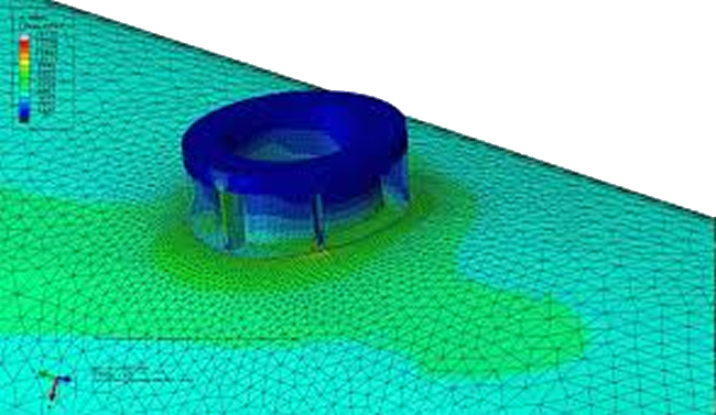
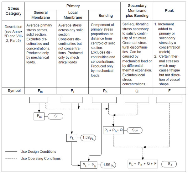
In demonstrating Protection Against Plastic Collapse and Protection Against Failure From Cyclic Loading: Ratcheting, one of the methods provided in Part 5 is a linear-elastic method. Because not all stresses will contribute to plastic collapse or ratcheting, a stress-at-a-point limit is not meaningful. Therefore, the stresses as calculated in the FEA in specific locations, called Stress Classification Lines (SCLs), are further linearized and classified. Then, those linearized and classified stresses are compared to appropriate allowable stress limits. This is the general basis behind what is known as the Hopper Diagram (because it resembles a grain hopper), shown below.
The topics of: where to place SCLs and how to validate them, how to linearize stresses, and how to classify stress is rather long and involved; it generally takes the better part of half of a day for me to go through these topics in my Part 5 Training Course.
Should I mesh my model with Solid or Shell Elements?
It really depends on the type of analysis that you are performing. I have used shell elements rather successfully for demonstrating Protection Against Plastic Collapse, Protection Against Buckling Failure, and Protection Against Failure From Cyclic Loading: Ratcheting using both the elastic analysis method and the elastic-plastic analysis method. However, shell elements are generally inappropriate for demonstrating Protection Against Local Failure. Furthermore, shell elements require additional stress concentration/intensification factors to be applied when demonstrating Protection Against Failure From Cyclic Loading: Fatigue; although the new Structural Stress Method for the fatigue of weldments can directly use the output from shell elements.
Stress linearization is definitely easier in shell elements because they are, by definition, linear in the through-thickness direction. However, the methods shown in Annex 5-A for linearization of stresses in solid elements are straight-forward to apply.
And either shells or solids may be used when applying the elastic-plastic methods for demonstrating Protection Against Plastic Collapse, Protection Against Buckling Failure, and Protection Against Failure From Cyclic Loading: Ratcheting.
What are the limitations of the elastic analysis methods and the potential problems?
The answer to this question is answered right in Part 5.
Article 5.2.1.2 says: For components with a complex geometry and/or complex loading, the categorization of stresses requires significant knowledge and judgment. This is especially true for three-dimensional stress fields. Application of the limit load or elastic-plastic analysis methods in paragraphs 5.2.3 and 5.2.4, respectively, is recommended for cases where the categorization process may produce ambiguous results.
Article 5.2.1.3 says: The use of elastic stress analysis combined with stress classification procedures to demonstrate structural integrity for heavy-wall ( ) pressure containing components, especially around structural discontinuities, may produce non-conservative results and is not recommended. The reason for the non-conservatism is that the nonlinear stress distributions associated with heavy wall sections are not accurately represented by the implicit linear stress distribution utilized in the stress categorization and classification procedure. The misrepresentation of the stress distribution is enhanced if yielding occurs. For example, in cases where calculated peak stresses are above yield over a through thickness dimension which is more than five percent of the wall thickness, linear elastic analysis may give a non-conservative result. In these cases, the elastic-plastic stress analysis procedures in paragraph 5.2.3 or 5.2.4 shall be used.
And Article 5.2.1.4 says: The structural evaluation procedures based on elastic stress analysis in paragraph 5.2.2 provide an approximation of the protection against plastic collapse. A more accurate estimate of the protection against plastic collapse of a component can be obtained using elastic-plastic stress analysis to develop limit and plastic collapse loads. The limits on the general membrane equivalent stress, local membrane equivalent stress and primary membrane plus primary bending equivalent stress in paragraph 5.2.2 have been placed at a level which conservatively assures the prevention of collapse as determined by the principles of limit analysis. These limits need not be satisfied if the requirements of paragraph 5.2.3 or paragraph 5.2.4 are satisfied.
What are the potential problems that can occur in the interpretation of the finite element analysis results?
The linear elastic methods involve a significant amount of interpretation of the results. It is possible to interpret the stress results in an unconservative manner. The elastic-plastic methods don’t suffer from this issue.
The other potential problem is in understanding the failure modes and the application of the loading scenarios for evaluating each. I addressed this issue in a previous blog post.
The other potential problem can arise in the handling of fatigue of welds. There are two methods available for demonstrating Protection Against Failure From Cyclic Loading: Fatigue for welds: the Fatigue Strength Reduction Method (FSRF) and the Structural Stress Method. I have seen the FSRF method applied incorrectly more than I have seen it applied correctly; it requires experience and know-how, especially in choosing an appropriate FSRF value. The Structural Stress Method is relatively new, and therefore the experience in industry with it is small. However, it is very robust and based on a wealth of experimental data.
What is the status of elastic-plastic methods in the ASME Code?
The elastic-plastic method is my preferred method for Protection Against Plastic Collapse. ASME PTB-1 states that the elastic-plastic method for demonstrating Protection Against Local Failure is the only method that is adequately robust; I agree with that assessment. I have also co-written a paper which highlighted some significant shortcomings of the elastic buckling analysis methods, and therefore I tend to prefer the elastic-plastic buckling method. The elastic-plastic Protection Against Failure From Cyclic Loading: Ratcheting and Protection Against Failure From Cyclic Loading: Fatigue are also quite robust. Especially for low-cycle fatigue, I think that the elastic-plastic fatigue method is superior to the elastic method, because there are no factors that need to be calculated.
Is it possible to replace the physical tests of a pressure vessel by FEA?
While I am generally a big proponent of saying that models don’t prove anything; in the context of design, FEA isn’t being used to prove anything, but rather to demonstrate that certain failure modes have been adequately considered. And, in the pressure vessel world, the design options are: rules, analysis or destructive proof tests. A proof test just isn’t practical for a multi-million dollar one-of pressure vessel.
The methods detailed in ASME Section VIII, Division 2, Part 5 do have a significant amount of experimental data to back them up. That work is all detailed in ASME PTB-1. That said, it is never a bad idea to place a strain gauge on a vessel and validate an analysis during the hydrostatic test. The catch, however, is that FEA is typically used for determining localized stresses in regions of high stress gradient, making it difficult to place strain gauges exactly where you want them to provide that validation – on account of the finite size of the strain gauge. We do, however, recommend in-service monitoring for vessels in severe cyclic service, such as coke drums.
Why is it that any analyst, with access to an FEA program and has successfully applied FEA in other fields, finds FEA for pressure vessels so difficult? What is it about FEA for pressure vessels that makes it unique?
I return to my original question to conclude this post. As can be seen by some of the questions and answers, the field of FEA for pressure vessels is rather complex and filled with subtle nuances. However, the best way that I have described it to people is as follows.
FEA for pressure vessels is a lot like a three-legged stool. The first leg is knowledge of mechanics of materials (including thin and thick-shell theory) and the finite element method. The second leg is working knowledge of the analyst’s particular software. And the third leg is a thorough knowledge of the pressure vessel Code. If the analyst is missing just one of those legs, they are sitting on a two-legged stool: not very useful.
Based on my experience, the leg most missing is that of the pressure vessel Code. My training course takes four days just to introduce the concepts of Design By Analysis in ASME Section VIII, Division 2, Part 5. Only a few engineers have made it their career to focus on this specialty. When I field questions on the Linked-In ASME PVP discussion forum or eng-tips.com, I often recommend to people that they secure the services of an engineer who specializes in FEA for pressure vessels. And we need to ensure that engineers are using the latest Code editions, because we are constantly making improvements to the methodologies.
If you would like more information on this blog you may post a comment for the author below. Or you may contact Trevor by clicking the link below.
Trevor also teaches a course titled ASME Section VIII, Division 2 – Part 5, Design-By-Analysis. View Becht Training.


