No Detail or Procedure is Trivial, or, Sophisticated Vibration Analysis is a VERY Cost Effective Diagnostic Tool
Today it is common practice in overhauls of large rotating equipment to spend many man hours in detailed planning, coordination, writing procedures, reviewing documentation, reviewing past photos, procuring and inspecting spare parts etc. We also review our past experience and put steps in place to mitigate past problems or errors. Now that we have a detailed plan, have purchased and inspected all necessary spare parts and have mitigated all potential known problems we simply give the plan to the machinery contractor to execute, right? If you have been responsible for large machinery repairs long enough, you have definitely learned to say one thing: “I have not seen everything,” and never to say another “Oh that could never happen here.” No matter how thorough we think our plan is, going in, missing even the slightest detail in the field can result in a failed start up or worse. Experienced oversight is essential because in the machinery world, nothing is trivial.
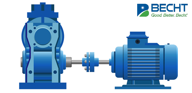
Here is a case example that yields a number of pragmatic lessons. A complete overhaul was performed on a large machinery train, which included an induction motor, speed increaser gearbox, centrifugal air compressor and all ancillary equipment. The compressor and gearbox were worked on site while the induction motor was removed and sent to an outside shop for reconditioning. The motor was returned to the site, reinstalled, aligned and coupled. Upon start up, the train experienced vibration alarms above 6 mils pk-pk at the motor drive end and gearbox input end. Plant personnel began the troubleshooting process. Was the gearbox repaired and assembled correctly with the proper parts? Was the motor reconditioned and assembled correctly? Was the motor installed and aligned properly with the correct shaft spacing? After a review of the repair procedures, alignment readings and a call to the motor repair shop, it was determined that all work items had been completed properly. However, the motor and gearbox continued to vibrate unacceptably near trip levels. Rather than asking operations to shut down the unit in order to begin searching for a yet to be identified problem, vibration analysis was used in an attempt to identify the cause of the vibration. This was accomplished using a 16-channel ZonicBook 618 analyzer to capture simultaneous data from all 16 monitored channels. All data was written to a hard drive on a laptop computer for subsequent analysis and processing.
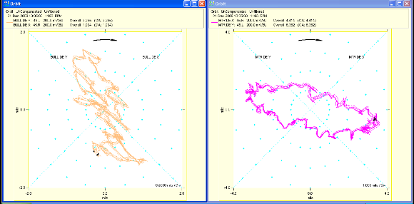
Discussion of Analysis – Orbit and time waveform plots of the motor drive end as well as the gearbox input end appeared extremely unusual. The 2 unfiltered orbit plots (Figure 1 below) show indications of a motor to gearbox coupling that is severely restricted or locked. In each case there are appx. 32 loops present. The orbit at left is the gearbox low speed shaft and orbit at right is the motor drive end.

Figure 1 – The Orbit Plots Above Show Possible Indications Of A Coupling Grid Lock Up. At Left Are 5 Rotations Of The Bull Gear Drive End Unfiltered Orbit. At Right Are 5 Rotations Of The Motor Drive End Orbit. Appx. 32 Loops Are Present In Both Orbit Plots. This Is Two Times The Number Of Rubber Stops Installed In The Coupling Grid End Turns.
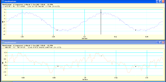
In Figure 2 below are unfiltered time waveform plots of the motor drive end “Y” probe (top) and the bull gear drive end “Y” probe (below). In both plots appx. 32 events take place between the 2 black keyphasor marks which indicate 1 shaft revolution. Again the number of events is 2X the number of rubber end float stops (16) installed in the flex coupling.

Figure 2– Shown Above Are Time Waveforms of The Motor Drive End Y Probe (top) And The Bull Gear Drive End Y Probe (bottom). In Both Plots, Appx. 32 Events Occur Between The 2 Keyphasor Marks. This Is Two Times The Number Of Rubber End Float Spacers Installed In The Coupling. This Is An Indication Of A Locked Or Restricted Coupling Grid.
There are definitely abnormal events occurring at 16 and 32 times running speed on both sides of this coupling! The client was contacted for (you guessed it) motor to gear coupling information. The client responded that the coupling was a “grid” type coupling with hubs that have straight teeth in the outside diameter and segmented spring grids in an “S” configuration that fit down in the teeth to transmit the torque. It turns out that for limited end float applications (such as this one) there are rubber spacer inserts available that are pushed down into the spaces formed between the end turns of the spring segments and the back of the teeth on both sides of the coupling. Because different limited end float coupling sizes require different amounts of end float, the rubber spacers are furnished long and must be cut to the correct length for the application.
Since the location and likely cause of the problem had been isolated, the train was shut down and the low speed coupling opened up. It was discovered that the rubber spacers all showed signs of distress and had been installed as furnished and not cut to length as required. This essentially “locked” the coupling, eliminating its ability to accommodate misalignment, resulting in the high vibration. New spacers were purchased, cut to the proper length and the coupling reassembled. The unit was started up and vibration amplitudes returned to normal levels.
Here are some of the lessons from this case:
- No detail or procedure is insignificant.
- Outside shops and field crews, even the “best,” don’t know all the nuances of every manufacture’s design or assembly procedures.
- Outside shops and field crews need to be provided ALL of the OEM’s procedures.
- Repairs conducted at outside shops or in the field are rarely successful without knowledgeable, involved oversight by the owner’s representative.
- Sophisticated vibration analysis is a very inexpensive diagnostic procedure and can save significant, valuable time in determining the root cause of machinery issues.
Becht Engineering Advisers have a wealth of experience in applying sophisticated vibration diagnostic techniques to successfully determine the root cause of some of industry’s most difficult and potentially expensive rotating equipment issues. Please contact us if you believe we might be of assistance.


