CFD Analysis With Scale Model Verification – A Proven, Cost-Effective Approach

Contributing Authors – Dave Dewees (Becht) and Dr. Keith Kirkpatrick (McHale Performance)
Reducing HRSG & Stack Pressure Drop to Improve Profitability
Many operating Simple and Combined Cycle HRSG (Heat Recovery Steam Generator) ducts and stack exhaust system designs can be optimized to reduce pressure drop, improve combustion turbine backpressure, improve performance and increase revenue. CFD analysis with Scale Model Verification is a proven and cost-effective tool for quantifying recoverable performance loss and improving generation plant profitability.
Combustion Turbine exhaust/HRSG/SCR ductwork, breeching and stack systems require careful attention during detailed engineering and design. While EPC Contracts typically include both performance guarantees and liquidated damage provisions which are highly dependent on Combustion Turbine backpressure, the design of this critical stack system is many times “farmed out” to 3rd party stack, HRSG or other less qualified suppliers. This practice can result in an un-optimized design with higher than necessary pressure drop resulting in reduced plant output and increased heat rate. In many cases, the EPC Contractor may be faced with Liquidated Damage payments due to the resulting performance shortfalls because of subcontracting this critical design. In extreme cases, the Owner may be unable to certify CEMS RATA due to excessive stack turbulence and non-compliant stack gas velocity profiles. In most cases this excess pressure drop is recoverable with minimal internal design modifications with retrofits that can be quickly designed, fabricated and verified prior to their installation using a proven approach which combines both Computational Fluid Dynamics (CFD) modeling with Scale Modeling to verify the CFD results.
How much lost performance can be recovered?
Modest reductions in stack system pressure drop can result in significant improvements in plant performance. For example, consider a typical 2X1 F class 670 Net MW / 6,550 Net Btu/kWh LHV combined cycle facility operating on natural gas. Reducing combustion turbine backpressure by only 1.5” H2O results in an additional 1.61 MW of plant output with a corresponding 15.72 btu/MWH improvement in heat rate (LHV). For a baseload facility operating with an 85% factor, this represents an increase in 12,000 MWH of annual generation with a corresponding reduction in fuel consumption for an estimated $551,000 annual financial improvement.
What are the key strengths (and pitfalls) of CFD modeling?
| Fig 1 – Unoptimized Stack Flow | Fig 2 – CFD Optimized Design with flow straighteners |
Tools such as CFD can be an important part of designing stack systems or system modifications. CFD is very attractive from a cost and schedule standpoint. It allows visualization of complicated phenomena and easy evaluation and comparison of alternate scenarios. CFD analysis is invaluable in making go/no-go decisions and advancing a design concept to near completion. However, CFD is seldom truly predictive without specific calibration. Even the most sophisticated engineering models embedded within commercial CFD programs involve numerous empirical constants that were determined for very specific cases. These models and constants do a remarkable job of providing reasonable results for a wide, wide array of problems, but they are approximations nonetheless.
When quantitative results are needed, verification, validation and likely calibration is essential to ensure that costly modifications work as intended. While commercial software continues to become more and more user-friendly, CFD is still a very complex tool and a robust and accurate simulation requires significant training and experienced CFD analysts. Verification and validation of the CFD model helps to protect the end-user against inadvertent input errors, or on-the-job training or “learning curve” errors made by the analyst. Figures 1 and 2 above show typical flow patterns in an exhaust duct and stack system CFD Model – both before and after the addition of turning vanes designed with the aid of CFD to reduce turbulence and pressure drop.
What is a physical scale model?
A physical scale model is a reduced size (1/20th to 1/40th scale) construct of an actual exhaust flow duct and stack, which maintains accurate relationships between the geometry and the flow, which is built quickly and at low cost using transparent materials such as plexiglass whereby experiments can be conducted to measure and visualize the actual geometry induced flow fields. Scale Modeling is a proven approach with many years of standing behind it. NIST (National Institute of Standard Technology) Fluid Metrology Group has a scale model facility [Scale-Model Smokestack Simulator (SMSS)] and utilizes scale modeling to validate CFD models for the progression of EPA Rata measurement techniques.
A scale model is designed by looking at geometric similarity through reproducing the Reynolds, Prandtl, and Grashof numbers, to ensure that the scale model will perform similarly to its full-scale counterpart. It provides one with a seeing and touching laboratory recreation that can be more satisfying than looking at color contour plots and animations of a virtual model. Smoke studies and turbulence measurements can be readily made and seen real time. It also provides real time confidence with the opportunity to walk around the 3-D scale model and examine flow patterns over baffles, around vanes, through perforated plates, and other internal structures, thus seeing the behavior visually. So, in summary, scale modeling is a long standing proven method to provide confidence in an exhaust duct/stack design by showing at a low cost a real representation of how the full-scale version will behave.
Trust but Verify the CFD model’s accuracy
The Russian Proverb, “doveryai no Proveryai” was made famous in December of 1987 after the signing of the INF Treaty with Mikhail Gorbachev when Ronald Regan said the phrase “trust but verify” to emphasize the extensive verification procedures that would enable both sides to monitor compliance with the proposed nuclear disarmament treaty. Having this mindset is essential in business as good business never requires trusting a person’s word and anyone who objects to being verified should never be trusted. This is also the case within the technical field of engineering and the tools used to predict design behavior as these processes and tools are used to provide the basis of trust for investment in a project
A proven cost-effective solution to address these issues is the addition of scale modeling to verify CFD predictions. While either CFD or physical scale modeling can be used independently, when used together they result in an extremely reliable solution with quantitative results that can assure success and the promised ROI.
As with many of the technological advances within the field of engineering, CFD modeling is an increasingly relied on method for simulating fluid behavior. CFD functionality and use has made tremendous strides in the past 20 years and continues to grow in sophistication every day. It provides the industry with a cost-effective means to test alternative designs and concepts, while providing a turnaround that keeps up with the fast pace needs of today’s market.
When CFD is strategically coupled to physical scale modeling, the result is a more flexible, cost-effective and accurate solution than if either method were used alone. The verification, validation and calibration provided by the scale modeling allows optimization to rapidly be performed with CFD, and with quantitative results that can be relied on to maximize the benefit of capital investment.
How do I mitigate the uncertainties?
While the internal modifications required to reduce stack system pressure drop are typically minimal including the possible addition of turning vanes, baffles or flow straighteners, the correct geometry and location of these modifications must be accurately determined if they are to be successful. However, the installation of these modifications can be time intensive, carry a high cost and can be risky especially if the actual performance improvements do not live up to the design predictions or expectations. When making a go/no-go decision it is prudent to include an extra step to verify CFD modeling results with scale model testing to “Verify” the “Trust” in the CFD model prior to installation. The minimal incremental time and testing costs are well spent to assure the project’s success and the return on investment promised to the plant owners and investors.
The successful use of these proven engineering and design tools, and ultimately the success of the project, rests mainly on the know-how and experience of the CFD analyst, engineering, design and scale modeling teams. The proven team of Becht Engineering and McHale Performance, with their long track record of problem solving and use of these tools, assures the successful implementation of stack pressure drop optimization projects to increase plant efficiency, reduce operating costs, improve environmental performance and profitability before going through the expense of executing the project.
CASE STUDIES
Case Study 1
With new regulations come new solutions and retrofit considerations. With the recent regulations on Sulfur and other criteria pollutants, many utilities chose to install Scrubbers and SCR Technologies in their coal-fired units. However, the installation of these technologies creates increased stack flow, therefore requiring additional work from the ID Fans. The existing fans typically do not have the excess margin required to handle the increased flow and utilities are forced to handle this situation by reducing the maximum load on the unit for an economic loss. An alternative to a costly replacement of higher capacity fans or adding expensive booster fans is to consider reducing the pressure drop of the flow in the stack and associated ducting by suitably modifying the flow passages.
This was the case when Tennessee Valley Authority (TVA) was exploring various solutions to change it’s stack configuration to accommodate the retrofit for their 1.7-gigawatt (GW) coal-burning Kingston fossil power plant composed of nine generating units located in Harriman, Roane County, Tennessee, on the shore of Watts Bar Reservoir. With this facility retrofit, there are eight (8) units feeding into a singular manifold then feeding into a single stack. With such flow complexity, it was realized that they needed an investigation that went beyond the boundaries of typical CFD capabilities on its own and elected to investigate their options using CFD coupled with Scale modeling. A Scale model was constructed on a 1:40th level to look at the various duct modifications and options to reduce pressure drop and optimize the flow paths before investing in any one or multiple options. The study looked at achieving pressure drop improvement by introduction of baffles and turning vanes at the entrance of the stack model. Figures 3 and 4 below illustrate the TVA scale model.
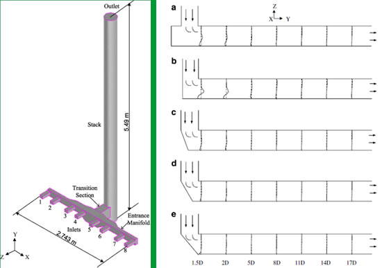 Figure 3 – TVA scale model conceptual design
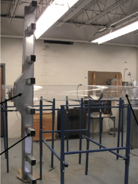 Figure 4 – TVA scale model Under Construction
From the study, it was proven that the conventional thinking that turning vanes would reduce pressure drop in this configuration actually did not result in any improvement. Instead, a baffle at the bottom of the stack, when positioned at 30%, resulted in a pressure loss coefficient improvement from 8.15 to 7.23, or .92 improvement which is 11.3%. This study provided TVA with key information that allowed them to make effective decisions on their retrofit solution.
Case Study 2
We are aware of an open cycle cogeneration facility that recently went into commercial operation. During commissioning and testing, problems were experienced during RATA Certification of the CEMS with the problem being identified as high turbulence and poor velocity distribution in the stack. The stack system included a typical HRSG transition duct, rectangular breaching and stack of standard design and dimensions but without baffles or turning vanes at the base of the stack. In troubleshooting the problem, the supplier developed a CFD model of the system and based on the results of the CFD modeling alone recommended the installation of a perforated plate in the stack. The plate was installed in the stack at the recommended distance above the breeching. As many of us would have predicted, even without the benefit of a CFD model, the addition of the perforated plate did not resolve the issue, but instead added an additional 1.5” of backpressure to the stack system and an unnecessary additional loss in output. Had the supplier tested his hypothesis and CFD model initially with a scale model, the cost and downtime associated with the installation of an ineffective retrofit that decreased plant efficiency and output could have been avoided. At the same time, an alternative retrofit could have been developed and tested prior to its installation had the supplier first tested his CFD “assumptions” with a physical scale model. The Owner is now faced the cost of additional engineering and retrofit work, emissions compliance issues and additional down time (lost revenue) to remove the perforated plate and to install the correct retrofit.