Design of Flue Gas Quench Sections
In the development of aircraft engines, physical tests are necessary to examine the overall performance of the engines. The exhaust gas from the test engine has high temperatures and often high pressures. The gas must be quenched before releasing to the atmosphere. A water-spray quench section is used for this purpose. The design of the quench section is to ensure that the maximum wall temperature of the quench section and the temperature of the quenched gas meet the design requirements. In addition, a quench section may be needed downstream of a boiler in a power generation plant to cool the flue gas from the boiler to a temperature suitable for chemical reactions to capture emissions, such as SO2 and NOx. Becht has completed a few projects to design quench sections for different flow conditions, using computational fluid dynamics (CFD) modeling. This blog presents two examples to highlight these projects.
The objective of CFD modeling was to optimize the number of spray nozzles and the arrangement of the nozzles (including nozzle layout and nozzle orientations) to meet the design requirements. Figure 1 shows the optimized nozzle arrangement for a quench section with an ID of 1 meter. There were three rows of nozzles; each row had six nozzles and each nozzle could be operated independently. The orientations of the nozzles were also optimized for optimal performance of the quench section. Any nozzles could be deactivated to meet the cooling requirement for different flow conditions of the exhaust gas.
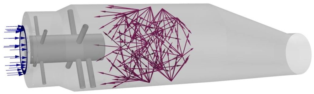
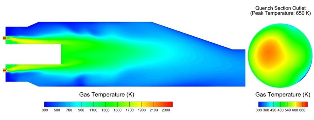
Figure 2 shows the distribution of the flue gas temperature on the vertical plane through the centerline of the quench section. The swirling flue gas enters the quench section through an annular ring at a high inlet velocity. The gas moves along the surface of the inner casing (the inner cylinder shown in Figure 1), which gives rise to a low velocity and reverse flow region near the wall of the quench section. A recirculation region with low velocities near the wall improves the penetration of the water droplets from the spray nozzles. This reduces the gas temperature in the region near the wall as shown in the figure. Along the axial direction of the quench section, as the water droplets evaporate, the gas temperature decreases rapidly. The average gas temperature at the model exit is 547 K which is 26 K lower than the design requirement of 573 K. The temperature distribution is relatively uniform at the quench section outlet. The local maximum gas temperature at the model exit is 650 K.
The wall temperature of the quench section is shown in Figure 3. The maximum wall temperature is 639 K which is located at the middle of the cylindrical section. Most of the wall has a very low temperature, due to the impingement and deposition of the water droplets on the wall. The maximum wall temperature is well below the design requirement of 1000 K. The results suggest that the nozzle arrangement shown in Figure 1 meets the design requirements.
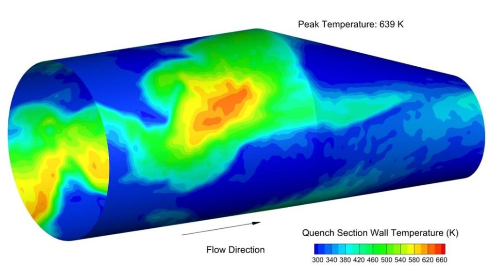
Figure 4 shows the geometry of a quench system that was designed to cool the flue gas from an incinerator to a temperature suitable for desulfurization reactions in a downstream spray dryer absorber (SDA). The system consisted of three flow passes. Spray nozzles were installed at the roof and rear wall of the third pass to cool the flue gas from 2000°F to 1000°F. CFD modeling was performed to determine the arrangement of the spray nozzles to meet the requirement of the exit gas temperature and to minimize the impingement of water droplets on the wall tubes to reduce tube corrosion and thermal fatigue due to potentially large thermal gradients of the tubes.
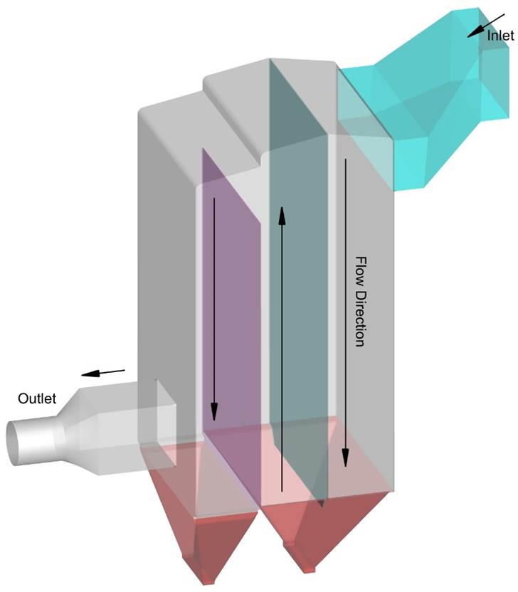
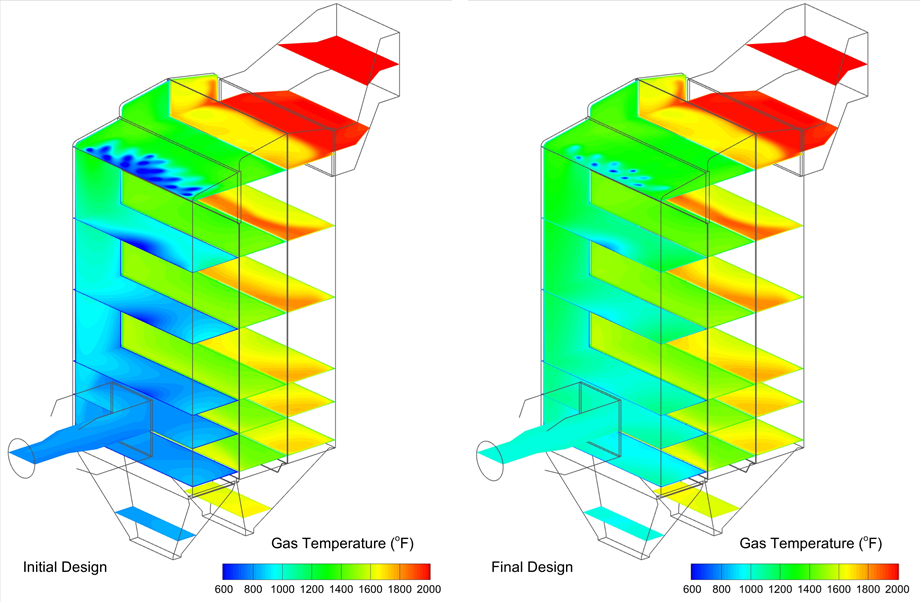
Figure 5 presents the gas temperature distributions for the initial design and final design of the nozzle arrangement. The gas temperatures at different elevations in each of the three flow passes are relatively uniform. At the inlet of the first pass, the gas temperature is considerably lower than that at the model inlet, due to a flow recirculation near the top of the pass. For the initial design, the average gas temperature at the outlet of the third pass is 786°F which is 34°F lower than the targeted gas temperature. For the final design, the average gas temperature is 7°F lower than the targeted temperature. It appears that the temperature distributions at different elevations in the third pass are more uniform for the final design than those for the initial design.
Table 1 shows the impingement rates of water droplets for the two cases. The water flow rates were different since the targeted gas temperature for the initial design was 820°F, instead of 1000°F for the final design. However, the percentage of the droplet impingement is much lower in the final design than that in the initial design. This is because in the initial design the spray nozzles were too close to the sidewalls of the quench section and all the nozzles were located at the roof of the third pass, while in the final design, the distances between the spray nozzles and the sidewalls were optimized and one row of the nozzles was located at the rear wall of the quench section.
Due to the confined space of the third pass, it was impossible to completely avoid the impingement of water droplets on the wall tubes. The small percentage of droplet impingement in the final design was deemed acceptable and this design met the design requirements.
Table 1. Droplet Impingement Rates for Different Designs.
| Case | Initial Design | Final Design |
| Total Water Flow Rate, lb/hr | 36,726 | 15,789 |
| Droplet Impingement, lb/hr | 5,214 | 689 |
| Droplet Impingement Rate, % | 14.2 | 4.4 |
The above two examples demonstrate how CFD modeling can be used to design different quench systems. The same approach can be utilized to optimize the design of other geometries when the gas stream needs to be quenched with water spray to targeted temperatures.