Piping and Instrument Diagrams (P&IDs): Part 1
Origin and evolution
Process plants require numerous types of equipment to produce the required products from the feed or raw material. This may involve moving gases, liquids and sometimes solids, and carrying out reaction, distillation or separation, cooling, heating and storage of feed, products, byproducts and supporting systems. Process equipment may include columns/towers, reactors, pumps, vessels/drums, compressors, furnaces, heat exchangers, gas or steam turbines, etc. Supporting equipment may include tanks, cooling towers, water treatment equipment, boilers, chemical storage/handling, fuel systems, air systems, flaring systems, fire protection, wastewater treatment equipment, fire protection equipment, loading/unloading arms, etc. A billion-dollar project can comprise up to 1,000 equipment items.
Process engineers develop schematic drawings that show how fluids move from point A to point B. These drawings will also show associated measurements, monitoring, controls, safety devices, etc. While several names and variations exist for these schematic drawings, this article will refer to them as piping and instrumentation diagrams (P&IDs).
Anyone that has been involved with P&IDs for front-end engineering design (FEED) or engineering, procurement and construction (EPC) projects may be familiar with the subject matter discussed here. However, for any engineer, owner or operator coming from a non-P&ID world to the P&ID world, this article will increase understanding of the subject and lessen the potential daily shocks.
Project Road Map
Demands such as “Stop making changes to the P&IDs” and “Get the process engineers off this project” may have been heard by those associated with a process plant FEED or EPC project.
These complaints are often valid. Process engineers and control systems (instrument) engineers tend keep improving on their designs, or even previous projects. Clients or the owner’s engineers also want to make design changes. The engineering and design of all other disciplines depends on what is in the P&IDs, which were sometimes referred to as the “Bible of the job.” While that phrase may not be used anymore, P&IDs are certainly the road map of the project.
Other engineering disciplines must know that the P&IDs are finalized so they can finish their own work. Frequently, other engineering disciplines plan their project staffing based on a known number of project P&IDs. Any late change to a P&ID requires others to redo their work and prevents them from finalizing their work in a timely fashion. This would be similar to an accountant manually completing a tax return while the client continues to submit additional expense receipts, income records, forgotten accounts receivables, etc.
In many cases, the construction team in the field have already begun plant construction—even a small change can be costly. Adding a ¾-in. drain valve in a line might not be significant on a multi-million- dollar project; however, if the subject line (piping spool) has already arrived in the field, such a change can be costly and frustrating to all involved, including the client and the EPC company.
Some process engineers are extremely capable as engineers but have no experience or regard for project cost or schedules. Some do not know how their P&IDs are used, or by whom, or they are fearful or hesitant to make timely changes until it may be too late. Some process engineers will argue that the system will not function properly if their proposed change is not implemented. In any case, design improvements never end.
Questions Remain
Questions remain about what causes engineers to make changes, when to freeze P&IDs so no preferential changes are allowed, and under which scenarios a change can be allowed even after the design is frozen. This is discussed in Part 2 of this article.
In the meantime, it may be useful to understand the inception of the P&ID, how it develops into a mature and complete P&ID, and the challenges in between.
P&ID origin. Many personnel only encounter a finished P&ID for a plant that is already in operation, rather than being involved in the development of the P&ID itself. The process varies from project to project and company to company.
In some engineering companies, the process engineer is responsible for the P&ID during the entire project, from FEED through EPC. In others, the process engineer participates only in the first pass before handing off the P&ID to another group, such as systems or process engineering. For the purpose of simplicity, this article assumes the former methodology.
FEED Phase
The P&ID is begun during a project’s FEED phase, where the goal is to produce a project cost estimate within 10% accuracy. Without a complete set of P&IDs, the FEED level project cost estimate cannot be accomplished.
In an ideal situation, process flow diagrams (PFDs) must be reasonably firmed before P&IDs are started; however, project team members cannot always wait for that. Many major equipment items may be known in the project’s early stages. As PFDs of these components are being developed, basic P&IDs can be started simultaneously. Examples of these known components include:
- Fractionation column
- Crude preheat heat exchanger train
- Acid gas recovery unit
- Air coolers
- De-methanizer, de-ethanizer
- Storage tank
- Large process compressor
- Boilers
- Deaerator
- BFW pump
- Instrument air compressor
- Air dryer.
If a licensed unit is part of the project, legal access to P&IDs of a project of similar size might be available. While the PFDs are being developed and heat and mass balances are taking shape, associated P&IDs may be started on a piecemeal basis for the above-mentioned components.
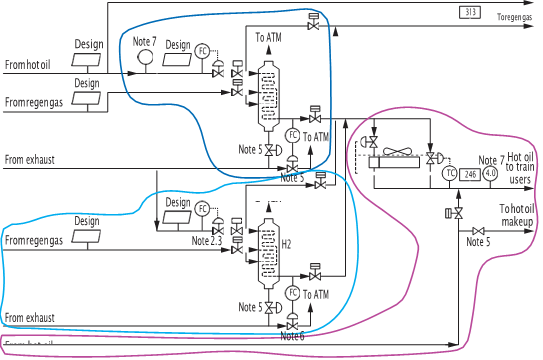
FIG. 1. A PFD for a waste heat recovery unit (WHRU). Three P&IDs will be made from this PFD
A typical PFD (FIG. 1) will produce multiple P&IDs, and an experienced process engineer will know how to carve out several P&IDs from a PFD by drawing different clouds for each. The process engineer can use a P&ID of a similar unit or system from a previous project as a starting drawing. It will be heavily marked to reflect the current project’s drawing and equipment numbering system. A control systems engineer will provide his/her input to reflect and implement the intended control scheme and for the measurement and control of necessary process variables, such as flow, temperature, pressure and level, as well as any other known instrumentation requirements.
Equipment title blocks at the top may be empty if the equipment sizing has not been finalized. Line sizes may or may not be known, and information on piping specification may not have been developed, so they must wait. It is also too early to add line numbers, so the P&ID is essentially a bare-bones drawing.
P&ID development. The first sketched P&IDs may not be quite ready, but the computer-aided drawing (CAD) group may have some free time between the PFD drafting so they can begin the CAD process. For many large projects based in a major engineering house in the U.S., P&ID drafting is done in high-value centers (HVCs) located mainly in Asian countries, such as India and the Philippines. When a sufficient number of these sketches are ready, they are scanned in the U.S. and sent to the HVCs.
The CAD supervisor processes the work, checks it, marks it for errors and omissions and then gives it back to the CAD team. Depending on the process engineer’s priorities, there may not be any movement on the P&IDs for days. As process engineering develops and evolves, PFDs are updated. The P&IDs may also be updated, but the process engineer’s priority is usually to issue the PFDs first, updating the P&IDs as time permits and continuing to create new ones.
P&ID Development Process
In the EPC business, it is common that P&ID creation is rarely fast enough to satisfy the project team. Even the official flow diagram index that tracks all known PFDs and P&IDs cannot keep up with the evolution. This PFD and P&ID development/evolution process can extend during the first few months of the FEED phase. P&IDs will be continuously updated and recycled through CAD drafting, checking and update processes. It is not uncommon for a P&ID to go through a dozen or more CAD cycles during this hectic FEED development stage. During the entire FEED/EPC process, a typical P&ID may go through 50 or more CAD cycles until it is finally issued “as-built” and turned over to the plant owner. Obviously, not all project P&IDs move together—multiple groups move at different speeds at different times. Some troublesome P&IDs will get separated from the herd and cycle through CAD more frequently. With hundreds of project P&IDs, keeping track of the different groups, troublemakers and loners becomes a thankless job.
As the scope change and evolution slows down, the PFDs are brought up to date, and they may be ready for the contractor’s internal review. The review helps the rest of the project team understand the extent of the scope of work and provides a bird’s-eye view of the project. The PFDs are then issued to the client for review and comment.
Increased tempo. At this stage, P&ID work will pick up speed. Process, control systems and piping will provide information that is now ready to be included in the drawings. Numerous data will begin appearing on the P&IDs.
A process may make configuration changes and add available equipment data, additional lines, line sizes, bypasses, startup lines, valve types, utility supply and return lines, relief valve requirements, additional control valves, pressure regulators, operational and maintenance blinds, and insulation needs, to name a few. Information such as pressure ratings, material of construction (if known), insulation required, piping specification changes, etc., will be shown on individual lines, although line numbers may not be assigned until later. There will be code breaks for piping, such as boiler code vs. in-plant piping, pipeline code vs. in-plant piping, and piping material change indication. Piping will also identify devices that do not fit as tagged mechanical equipment or do not fall within piping specs. These are noted as E/I (engineered item) or S/P (specialty item).
In cases of pumps taking suction from vessels, a process engineer will add the elevation of the vessel on the P&ID to ensure that adequate net positive suction head (NPSH) is available to prevent a pump from cavitating. Increasing this elevation at a late stage can cause complications because dozens of drawings would need to be changed.
Other information includes unit battery limit valves; special requirements such as slopes, symmetrical piping, no pockets, gravity flows, minimum or maximum distances, oar seal open/closed valves and/or lock open/closed valves; and a tie-in point to connect the system to the existing plant and/or future requirements, or to a second train that may be built later.
Control systems (instruments) will add known loops, preliminary control valve sizes, estimated relief valve sizes, distributed control system (DCS) requirements, level bridles, etc. Significant informal discussions take place between process and control systems to determine emergency shutdowns (ESDs), interlocks, trips, overrides, cascade controls, feed-forward signals, auto starts and depressuring valves, among others. These are then implemented on P&IDs by a control systems engineer. Emergency shutdown (ESD) systems will also be implemented by control systems.
On the first draft of a P&ID, there will only be a handful of instrument bubbles. Within the first few weeks, dozens of instrument bubbles will clutter the P&ID, and more will come as design progresses. If it is being considered, the decision whether to use a high-integrity pressure protection system (HIPPS) can take a long time and even extend into the EPC phase. Such additions/changes can occupy significant space on a P&ID. An experienced process engineer can anticipate such an explosion of information and plan the P&ID layout accordingly. Failure to do so will result in a crowded and illegible P&ID.
Although no equipment is purchased in the FEED phase, the size of rotating equipment will be known; therefore, equipment protection devices can be identified jointly with the respective mechanical engineer and added to the P&IDs. Large rotating equipment items have complex lube oil and seal oil skids, which are furnished by the vendor. These will have significant interface with the plant control systems. A large gas turbine may be shipped along with up to 20 supporting skids that must be connected with other components, as specified by the vendor. Some process requirements must be shown with separate details and with clarification notes. A P&ID may not have any such notes at the beginning, but can easily have 20 or more such notes when it is finished.
P&IDs are not scaled drawings, however, and some aspects do consider relative geometry of the plant. For example, P&IDs show fire water loops, utility distribution and interconnecting piping that are based on actual plant layout and geometry.
Hundreds of items are engineered by various parties for P&IDs at different times and must be coordinated for suitability by themselves, as well as in conjunction with other parts. This requires constant written and face-to-face communication between all engineering teams, especially process, control systems, process safety and piping.
Smart plant or intelligent P&IDs. Before discussing smart plant P&IDs, it is interesting to explore how P&IDs were created and used before the digital age.
P&IDs and many other project drawings were manually drawn on plastic. This transparent material (mylar) allowed various cycles of writing and erasing. Full-size, adjustable drafting boards were required to lay the mylars flat, and a task force project area could be filled with dozens of such drafting boards. Draftsmen (almost all were men) used various stencils and tools to draw various shapes. If certain portions of drawings went through too many drafting cycles, a new mylar would need to be made from the old one. Making copies of drawings could take time, as it had to be done by special machines in a reproduction room. These rooms served all in-house projects, so they were constantly busy with project managers jockeying and hustling to get their drawings copied on a priority.
Today, any size drawing can be plotted with just a couple of clicks on a local plotter. P&IDs are the basis of the project, defining work and providing data for many other disciplines. In pre-digital days, technicians manually extracted this data to generate their own deliverables. This included information on control valves, relief valves, manual valves, measurement devices, transmitters, gauges, etc.
Piping engineers will initially make plot plans and piping layouts and create a line list (sometimes called a line designation table) showing line size(s), piping specs, operating and design pressures and temperatures, insulation needs, abnormal conditions, etc., for each line. Some line lists also show normal and design flowrates. Electrical engineers know the motor drivers needed, and civil/structural engineers know the foundation requirements. This was done manually, item by item.
As the P&IDs progressed, a real plant model would be made using plastic pipes and other components. Typically, this would be assembled on a table at a scale of 3/8 in./ft and was often referred to as a “3/8th model.” To move it, the model was divided into table-sized portions. If any of the P&ID information changed, the manually collected data (and, in some cases, the model) were changed. Therefore, it was important for users to keep track of the changed items and then correct or update their own data.
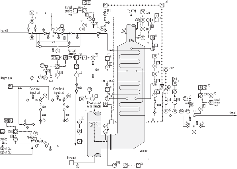
FIG. 2. In a smart plant P&ID, data is extracted automatically by downstream disciplines and updated automatically when the P&ID is updated, providing data quality and dependability
The smart plant P&ID is more than just a CAD. With smart plant software, all information shown on the P&ID (FIG. 2) is categorized and digitally stored. The data is extracted automatically by downstream disciplines and updated automatically when the P&ID is updated, providing data quality and dependability. This saves significant job hours and reduces the frustration of encountering gaps and conflicts.
Smart plant software, which continues to evolve, flags any discrepancies in connectivity of lines and signals going from one P&ID to the other. Unlike in the presmart plant era, all team members have access to the real-time P&ID data, enabling simultaneous and joint review and discussion by teams around the world.
The smart plant P&ID also facilitates the making of virtual 3D models that are reviewed for completeness, ease of access and operability. Labor-intensive plastic models have become history. Additionally, older versions of P&IDs can be easily accessed as required—this helps clarify who changed the P&ID and when. The smart plant can also extract equipment data from the title blocks on the P&ID, which must be kept up to date.
P&ID Issue Sequence
At a suitable time, an internal P&ID review will be conducted. After a handful of CAD cycles, and on the agreed scheduled date, the P&IDs must be issued to the client for review and comments. A joint review will then be conducted with numerous parties from the contractor and owner side. The review timing must be planned sufficiently in advance so that non-resident parties can attend, as this is technically the last chance for owners to make any comments. In reality, new comments keep coming even after the review. A thorough process design basis issued early can help avoid late comments, such as, “We need three 50% pumps and not two 100% pumps,” or, “One of our existing boilers has not worked properly, so your boiler needs to provide 50,000 kg/hr of high-pressure steam to the existing plant.” The latter comment may seem insignificant, but it affects the boiler specs as well as the boiler blowdown system, steam header size, BFW pumps, deaerator, demineralized water (DMW) makeup, the DMW plant capacity and possible upstream water treatment systems. Later, a notification may arrive that the existing plant will return 25,000 kg/hr of condensate. This will again change almost everything mentioned.
In any case, the P&IDs are then issued for a FEED hazard and operability study (HAZOP). Ideally, no preferential changes take place after the joint review, but changes continue to happen for reasons described in Part 2. Most of the changes can be accommodated in time, but big changes will have cost and schedule implications. Project managers do their best to track and prevent such instances.
Using a master P&ID. After a complete set of P&IDs is adequately defined for a unit or a system, a master P&ID set is maintained. This hard-copy, full-size set is located in an area where everyone on the project has visitor’s rights. Only process engineers, control systems (instrument) engineers and piping engineers/designers should make changes to these drawings. Mechanical engineers may make limited marks. In some types of EPC projects, mechanical engineers also function as process engineers.
The master P&ID set contains the latest design information. Previously issued digital copies can quickly become obsolete. There can be a lag time of up to 2 months between the time when an outside party’s comment is accepted and the time when it appears on a next digital issue. At a predetermined time, the marked master is sent to the drafting group to incorporate the changes. Sometimes, the marked changes clutter the drawing so much that it is sent to CAD drafting ahead of its time. Some engineers collect marks on their own mini-master set and periodically transfer those marks to the real master. Others frown upon that practice, as most parties want to see the change reflected on the drawings in real time.
HAZOP Integration
What one engineer may think is an insignificant change can have a big impact on other contributors. To avoid unending updates to design, most projects implement a P&ID freeze date that usually coincides with the “issued for HAZOP” date. Engineers are allowed to make reasonable changes until that date, when the master is pulled and sent to drafting for updates and issue for HAZOP.
TABLE 1 shows a snapshot of a HAZOP closeout report. The 827 HAZOP action items represent only half of the total action items for the multi-billion-dollar project. Approximately 4 month–5 months after the HAZOP, 138 items were still open. Late closure of these items can impact P&IDs.
|
Unit |
Contractor action | Manual procedure | Commissioning/ QA-QC | OPCO/
training |
Open |
Closed |
Total |
| Total | 75 | 54 | 7 | 2 | 138 | 689 | 827 |
| Percentage | 9.1% | 6.5% | 0.85% | 0.25% | 16.7% | 83.3% | 100% |
TABLE 1. HAZOP action items close-out status
A photocopy of the master is used while the comments are picked up, checked and a new master is placed. At the same time, the temporary master continues to gather new comments.
Some of these can include valid new comments from the client. If the CAD work associated with these new comments is minor, then the CAD supervisor and the project engineer will agree to incorporate the comments. However, if the CAD effort proves to be significant, then incorporating the comments creates one or two more CAD cycles, delaying the planned issue date. In such a case, incorporating comments from the temporary master will be deferred until the next issue. When a new master is placed, the comments not picked up are transferred to the new master. It is not uncommon for the new master to already be cluttered with such pending marks on its first day.
To avoid any misunderstanding, the client must be forewarned that their comment has been accepted but will not appear until the next issue, with the explanation of the reason.
Click the link below to contact a Becht expert regarding your future plans:

