Process Compressor Gas Seals
This is the second article in a planned series where questions related to process machinery will be addressed. The intent of these articles is to answer general questions you may have about the machinery that you work with or manage on a daily basis. In each article we will address different systems associated with the operation and maintenance of process machinery. Your comments on this article would be greatly appreciated. Or, if you have suggestions for additional topics of interest, you can reach us via comment at the end of the blog.
PROCESS CENTRIFUGAL COMPRESSOR GAS SEALS
The purpose of this article is to outline the basic components and operation of a compressor gas seal system. Compressor process seals are designed to seal the rotating assembly in the stationary compressor case to prevent the process gas in the compressor from getting to the atmosphere and to prevent the atmosphere from getting into the process gas. Gas seals, as compared to oil seals, are relatively new in the machinery world. Each type of seal, gas or oil, has their relative advantages and disadvantages; an analysis which would take an article of its own to discuss or debate. It is safe to say that today’s trend is to purchase new compressors with gas seals and often to replace existing oil seals with gas seals.
A typical gas seal system is comprised of three main sub-systems:
- Seal and separation gas supplies and vents
- Control panel with piping to and from the seals
- The gas seal housing, including seal faces/surfaces, and/or bushing
The seal gas used as the sealing medium is usually a clean, dry and cool gas that is compatible with the process gas being compressed. The seal gas supply pressure MUST be a higher pressure than the compressor seals will ever encounter. The “clean, dry and cool” specification can be accomplished by installing filters, driers and coolers in the seal gas supply line. The separation gas is usually an inert gas such as nitrogen and should be dry and cool. The vent systems usually tie into a flare system or some system where the leakage can be disposed of safely.
The control panel is composed of differential pressure regulators, differential pressure gauges, flow gauges, tubing, block valves and fittings. One common problem with gas seal control panels is they are built with cost, ease of fabrication and ease of installation as priorities rather than “operator friendly” as the main objective. We will discuss an improved user friendly design later in the article.
Gas seals are designed for many different applications and vary in design from one machine to another and from one manufacturer to another. Some have more stages of seals and different types of sealing components such as bushing seals and contacting faces, or floating faces and lift off seals. However all gas seals function using the same principal: “DIFFERENTIAL PRESSURE”.
HOW DO THEY WORK?
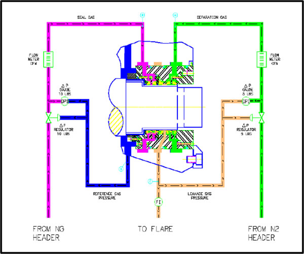
The explanation of functionality can better be conveyed using the simplified drawing (seen on page 2) of a gas seal control panel that Randy and Stanley designed; a control panel that graphically shows how the seal work. With a few additions of set points, limits, and control variables, this control panel/diagram becomes a simple, easy to understand, working panel for compressor operations personnel. As simple as this concept may seem, we have seen installations where the seal gas panel, the separation gas panel and the vent gas panel was separate from each other, with some panels on the machinery deck, and another panel at grade, making day-to-day management of the system considerably more difficult than necessary.
The drawing on Page 2 shows a section of the compressor shaft, which rotates and the seal and seal housing, which are stationary. The process gas is in the area to the left of the drawing and the atmosphere is in the area to the right of the drawing. The color coding is as follows:
- Reference gas pressure (seal operating pressure) is shown in BLUE
- Seal gas is shown in PURPLE
- Separation gas is shown in GREEN
- Leakage gas is shown in TAN
The reference gas is the process gas inside the compressor. Its pressure is usually balanced from the discharge seal to the suction seal so both seals are operating at the same pressure. The reference gas is piped to the gas seal control panel where it is connected to a differential pressure gauge and a differential pressure regulator, and used as a control signal.
The seal gas supply is piped to the gas seal control panel where it is filtered, dried and cooled and then connected to the flow control of the same differential gauge and differential regulator as the reference gas. This regulator will maintain the seal gas supply pressure to the seal at a higher pressure than the reference gas. The seal gas differential pressure for this application is set at 10 PSID. This PSID setting may vary with different applications. The higher the PSID the more room for process operation variability; however, the higher the PSID the more leakage into the compressor and vent. The differential gauge will normally read 10 PSID assuring that the differential regulator is functioning properly. The seal gas flows through a flow meter that indicates the amount of seal gas being used – which is a key indicator of the health of the gas seal. (When the seal gas flow increases above the normal leakage rate it indicates that the gas seal has a problem.) From the flow meter the seal gas then flows into the gas seal housing. In the seal housing seal gas will then flow in two different directions; some will flow across the seal through the close clearance of the seal faces or bushings and into the compressor, while most of the Seal Gas will flow across the seal through the close clearance of the seal faces or bushings into the leakage gas or vent area. The differential pressure will be greater between the seal gas and the leakage gas than between the seal gas and the reference gas.
The seal gas flows into the compressor because the seal gas is at a higher pressure than the reference gas pressure! DIFFERENTIAL PRESSURE!
The leakage gas, highlighted in TAN, is the combination of the seal gas leakage and separation gas. The leakage gas is piped to the gas seal control panel where it is connected to a differential gauge and a differential regulator and used as a control signal. The leakage gas is also piped to a vent or to a flare header to dispose of the leakage. This leakage gas piping has a flow meter that indicates the amount of sear gas and separation gas being vented which, when trended, is a key health indicator of the gas sear.
The separation gas supply, usually nitrogen, is piped to the gas seal control panel where it is filtered and dried and then connected to the flow control of the same differential gauge and differential regulator as the leakage gas. This regulator will maintain the separation gas supply pressure to the seal at a higher pressure than the leakage gas. The separation gas differential pressure for this application is maintained at 5 PSID. This PSID setting may vary with different applications. Higher PSID provides more room for upsets. However, the higher the PSID, the more separation gas is lost into the leakage gas and to the atmosphere. The differential gauge will read 5 PSID assuring that the differential regulator is functioning properly. The separation gas flows through a flow meter that indicates the amount of separation gas being used. This flow is also a key health indicator of the gas seal. From the flow meter the separation gas enters the seal and will then flow in two different directions, some will flow across the gas seal through the close clearance of the seal faces or bushings into the leakage gas, and some will flow across the gas seal through the close clearance of the seal faces or bushings to the atmosphere. The flow of the separation gas to the atmosphere prevents oil or air from entering the gas seal.
The separation gas flows into the leakage gas because the separation gas is at a higher pressure than the leakage gas pressure! DIFFERENTIAL PRESSURE!
The combination of data from a well-designed gas seal control panel’s differential pressure gauges, flow meters and differential regulators provide operators with real-time information necessary for timely fine adjustments of the seal operation, and machinery reliability engineers with trend data for effective predictive health monitoring of the seal.


Thank you for thoroughly explain exactly what a centrifugal compressor gas seal is and what its function are.
It is a comprehensive blog post on process compressor gas seals. Working of process compressor gas seals is also worth reading. Thanks for sharing this with us!