Redesign of the Heating System for a Sulfur Storage Tank
Storage tanks are widely used in refineries and sour gas processing plants for temporary storage of molten sulfur produced in the sulfur recovery units. These tanks are typically constructed with carbon steel and are cylindrical with external insulation on the side and the roof. Corrosion may occur on the external and internal surfaces of the tanks. The most common cause of external corrosion is water from the ambient; water penetrates the insulation layer through damaged areas and is trapped between the tank surface and the insulation. If the surface temperature is lower than the boiling point of water, the water will not evaporate and consequently will corrode the surface. Internal corrosion occurs when sulfur vapor condenses and deposits on the interior walls in the vapor space above the liquid level in the tank, due to inadequate heating leading to the temperature in the vapor space lower than the sulfur melting temperature. Other major mechanisms for internal corrosion of the tank are associated with H2S released from liquid sulfur. H2S may oxide to form SO2 if oxygen is present in the vapor space. SO2 may further react with water in the vapor space to form highly corrosive sulfurous acid which will condense on the interior walls of the tank if the wall temperature is lower than the dewpoint of the acid. The dewpoint of sulfurous acid depends on the concentrations of water vapor and SO2 in the vapor space, which typically is much lower than the melting point of elemental sulfur. Therefore, to avoid corrosion of the tank, adequate heating is critical to maintaining the interior wall temperature of the tank higher than the melting point of sulfur (approximately 246°F) and the exterior wall temperature of the tank higher than the boiling point of water (212°F).
The first generation of the heating system for a storage tank consists of an internal submerged steam coil that only maintains the liquid sulfur temperature and ignores the temperatures of the wall and roof surfaces. Improvements to the first-generation design include exterior steam coils mounted on the roof to keep the roof temperature higher than the melting temperature of sulfur. The improvements may also include interior steam coils mounted close to the walls in the vapor space above the liquid level in the tank. The state-of-the-art design of the heating system for a storage tank features an external heating jacket to heat the tank sidewalls and roof, that utilizes a heating medium, typically saturated steam, to circulate through the jacket. This type design has a proven record of successful sulfur tank heating applications and many tanks utilizing this design find limited corrosion issues. However, the capital cost associated with this design is considerably higher than the other designs.
This blog deals with a redesign of the heating system for a sulfur storage tank. The existing design is equipped with a submerged steam coil above the floor of the tank and an interior steam coil mounted close to the walls in the vapor space of the tank. There is no heating system provided for the tank roof. The steam coils provide heat to the molten sulfur to maintain the liquid sulfur above its melting point. However, the existing design of the steam coils does not provide adequate heating for the sidewalls of the tank in the vapor space and the roof to ensure that the sidewall and roof temperatures of the tank are higher than the minimum temperature requirement. Due to widespread corrosion throughout the tank resulting from acid formation and solid sulfur deposition on the cool wall and roof surfaces, the tank must be replaced after an operating life of several years. Storage tanks in similar service typically last for 20 or more years.
We conduct a computational fluid dynamics (CFD) analysis to redesign the existing heating system to determine if modifications or enhancements of the existing coil design can improve the ability to maintain the tank wall and roof temperature above the melting point of sulfur such that the operational life of the tank can be extended.
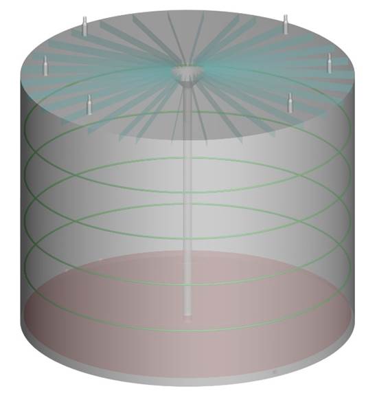
Figure 1 illustrates the CFD model geometry of the tank for the existing design of the wall coils. There are four steam coils in the vapor space. The floor coil is modeled as a heating plate. There are six vents around the circumference of the roof. A steam sweep nozzle is located at the center of the roof. Steam injection is utilized to sweep the tank such that the vapor space maintains an atmosphere with H2S concentrations lower than the lower explosive limit (3.5 vol.% at 280°F in air). The model includes roof rafters and a center support column. At the top of the center column, there is a cone which supports the roof rafters. The roof and the top edge of the cone form an annulus where the steam from the steam nozzle exits and spreads to the vapor space of the tank through the gaps between the rafters. The improved design includes additional steam coils mounted close to the walls of the tank. The existing design of the submerged steam coil above the tank floor remains unchanged.
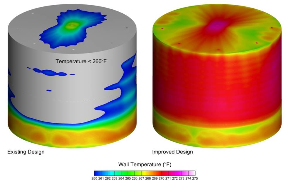
To minimize corrosion of the tank, the industry practice is to maintain the metal temperatures of the tank wall and the tank roof higher than 260°F. This temperature is used to compare with the predicted temperatures of the wall and the roof to determine the suitability of the improved design of the wall coils. Figure 2 compares the wall temperatures of the existing and improved designs of the heating system. For the existing design, there is a large region, as shown in grey, where the sidewall and roof temperatures are lower than the desired temperature of 260°F. For the improved design, the sidewall and roof temperatures are all higher than 260°F. For both designs, the floor of the tank has temperatures greater than 260°F which is higher than the inlet temperature of the liquid sulfur due to the heat transferred from the floor coil. The entire tank in the improved design has metal temperatures higher than the required temperature of 260°F. Note that the temperature distribution on the walls of the tank for the existing design is largely affected by the flow rate of the sweep steam, since the heat from the wall coils is relatively small and the sweep steam provides additional energy to maintain the vapor temperature, at least in the region near the roof of the tank. In contrast, for the improved design, the effect of the flow rate of the sweep steam on the temperature distribution of the metal is insignificant, because the energy provided by the wall coils heats up the vapor phase, including the steam.
Based on the CFD modeling results discussed above, we can conclude that by including additional interior steam coils in the tank, the tank wall and roof temperature can be maintained above the melting point of sulfur.
Keywords: Computational Fluid Dynamics, CFD, Sulfur Storage Tank, Heating System, Corrosion.


