Evaluation of Degraded and Nonconforming Conditions For ASME III and B31.1 and B31.7 Class 2 and Class 3 Pressure Boundary Nuclear Plant Components
1. Definitions
1.1 Degraded Condition
A degraded condition as defined in NRC Inspection Manual 0326 Paragraph 03.02: “A degraded condition is one in which the qualification of an SSC or its functional capability is reduced. Examples of degraded conditions are failures, malfunctions, deficiencies, deviations, and defective material and equipment. Examples of conditions that can reduce the capability of a system are aging, erosion, corrosion, improper operation, and maintenance.”
1.2 Nonconforming Condition
A nonconforming condition as defined in US NRC Inspection Manual 0326 Paragraph 03.06: “A nonconforming condition is a condition of an SSC that involves a failure to meet the CLB or a situation in which quality has been reduced because of factors such as improper design, testing, construction, or modification. The following are examples of nonconforming conditions:
- An SSC fails to conform to one or more applicable codes or standards (e.g., the CFR, operating license, TSs, UFSAR, and/or licensee commitments).
- An as-built or as-modified SSC does not meet the CLB.
- Operating experience or engineering reviews identify a design inadequacy.
- Documentation required by NRC requirements such as 10 CFR 50.49 is unavailable or deficient.”
2. Degradation by Wall Thinning
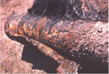
2.1 Root Cause
Degradation by wall thinning can be the result of corrosion (including microbial-influenced corrosion MIC), erosion (or wear), or the combination of corrosion and erosion such as in flow-accelerated corrosion (FAC).
2.2 Evaluation Procedure
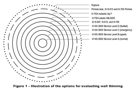
The various levels of evaluation are illustrated in Figure 1, and are as follows:
- Level 1 – Evaluate whether the wall loss is within the mill tolerance of the component, as given in material specifications or fabrication specifications.
- Level 2 – Evaluate whether the wall loss projected until the next inspection or repair is within the minimum wall thickness required by the design Code for all Service Load combinations. In the case of piping, this is illustrated by concentric circles III NX-3600 Service Levels A, B, C, and D (where III stands for ASME III Div.1, and NX stands for NB, NC, or ND).
- Level 3 – Evaluate whether the wall loss projected until the next inspection or repair is within the limits of the following ASME XI Code Cases, within the bounds of applicability of NRC Regulatory Guide 1.147:
- N-513 for moderate energy pipes and certain pipe fittings, including a pinhole leak.
- N-597 for high energy pipes and certain fittings, excluding a pinhole leak.
- N-705 for moderate energy pressure vessels, including a pinhole leak.
- N-806 for buried pipe, operating below 200oF, excluding a pinhole leak.
Note: There are currently no ASME XI Code Cases for the evaluation of wall thinning in high energy vessels, pump casings, or valve bodies. In this case, proceed to a Level 4 evaluation.
- Level 4 – Evaluate whether the wall loss projected until the next inspection or repair qualifies by elastic limits, or elastic finite element analysis (FEA) in accordance to NX-3200 (ASME III Appendix XIII as of the 2017 edition).
Note: When applying FEA to wall-thinning it is recommended to impose a minimum acceptable projected wall thickness, regardless of stresses, in the order of 1/16 in. to prevent pinhole leak.
- Level 5 – Evaluate whether the wall loss projected until the next inspection or repair qualifies by inelastic limits, or inelastic finite element analysis (FEA) in accordance with ASME III Appendix F (ASME III Appendix XX as of the 2017 edition).
3. Degradation by Cracking
3.1 Root Cause
Degradation by cracking can be the result of a fabrication weld flaw, corrosion (including stress corrosion cracking), fatigue, or a combination of any of these three causes, for example environmental fatigue.
3.2 Evaluation Procedure
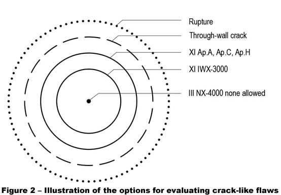
The various levels of evaluation are illustrated in Figure 2, and are as follows:
- Level 1 – Evaluate whether the crack-like flaw is within the fabrication allowance of ASME III NX-4000.
- Level 2 – Evaluate whether the crack-like flaw is within the flaw size limits of ASME XI IWX-3000, within the limitations of NRC 10CFR50.55a(g).
- Level 3 – Evaluate by fracture mechanics whether the crack-like flaw is within the limits of ASME XI Appendices A, C, and H.
4. Thermal Expansion Over-Stress for Piping
4.1 Root Cause
A thermal expansion over-stress is one of several types of actual or postulated overloads that are non-conformances. A thermal over-stress is a nonconformance which can be the result of an accidental interference, a damaged support or snubber, excessive pipe-to-support friction, the discovery of a design calculation error, or other causes by which the B31.1, B31.7, or ASME III design flexibility (expansion and contraction) stress equation limits are exceeded.
4.2 Evaluation Procedure
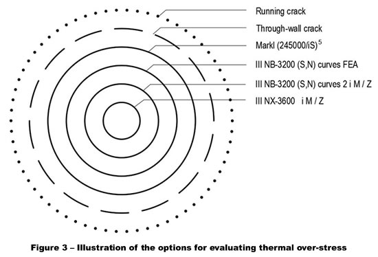
The various levels of evaluation are illustrated in Figure 3 and are as follows:
- Level 1 – Evaluate whether the over-stress exceeds the ASME III NB-3200 (S,N) fatigue curve, using S = ½ (2iM/Z) as the stress amplitude (not to exceed twice yield at operating temperature), and N = the number of cycles of over-stress expansion and contraction.
- Level 2 – Evaluate whether the over-stress component meets the fatigue analysis rules of ASME III NB-3200 using elastic finite element analysis.
- Level 3 – Evaluate whether the number of over-stress cycles is well below the Markl cyclic fatigue crack correlation Ncrack = (245,000 / iS)5. A factor of safety of 2 on stress, or 1/(1/2)5 = 32 on cycles may be applied in this evaluation.
If you have a question relating to this blog, you may post a comment for the author at the bottom of this page. If you would like to submit an Information Request please click below: