Stresses Beyond the ASME B31 Code Stress
Far too often, piping engineers fail to recognize that their responsibilities extend beyond simply meeting the code. The ASME B31 piping codes caution, “the code is not a handbook and cannot substitute for education, experience, and sound engineering judgment.” There are many different ways a piping system can fail that are not fully addressed in the code. This blog will address one such way.
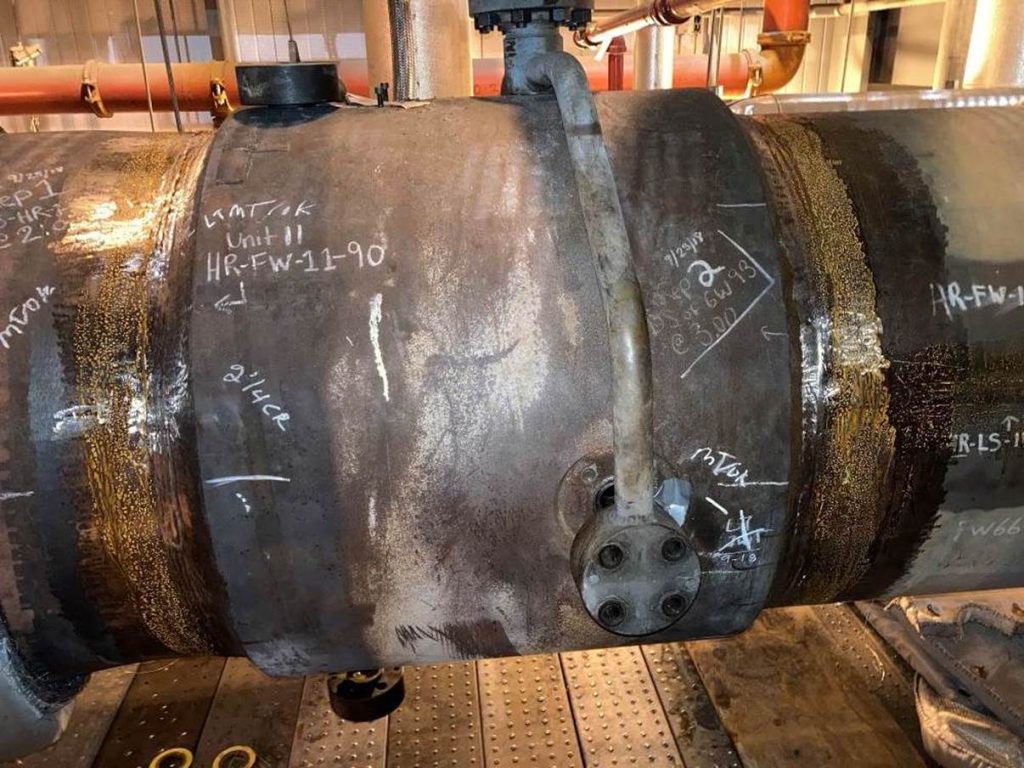
This case study involves a combined cycle power plant that went into commercial operation in 2003 and has well over 100,000 hours of operation. The combustion turbines cycle over 100 times per year to meet market demand. During cycling, the hot reheat steam bypasses the steam turbine and is routed to the condenser thru a pressure control valve and desuperheater. This plant has a history of cracking in the downstream pipe to desuperheater welds over the last several years.

Evaluation of this piping utilizing B31.1 based piping stress analysis showed a sustained stress of less than 50% of the code allowable and an expansion stress of less than 10% of the code allowable utilizing SIF (Stress Intensification Factors) of 1.5 at this location due to the tapered transition. The material is Grade 22 alloy steel, one with a long history of good service in the industry, not a Creep Strength Enhanced Ferritic (CSEF) steel that has noted industry issues. From the code design standpoint and in general, the system was well designed and should last almost forever, even with being in a hot reheat bypass service with its frequent operation and temperature transients.
However, the detail that was not accounted for in the design of this 36 NPS pipe and component was that the thickness of the pipe was 5/8” and the thickness of the desuperheater was 3½”. The taper of the desuperheater weld end followed the standard B16.25 envelope and this was reflected in the 1.5 SIF, all per code. A “code-based” designer would say it’s acceptable and a good design, but an experience- based designer with a good understanding of how things perform in service and where problems have occurred, should start to question whether the thickness difference would cause trouble and investigate it further.
In actuality, there are two types of stresses in this application that are not explicitly accounted for in most piping codes (Note: ASME Section III Subsection NB Class 1 piping rules do explicitly address these). The first is the discontinuity stress. B31.1 defines discontinuity as “a lack of continuity or cohesion; an interruption in the normal physical structure of material or a product.” But it says nothing about discontinuity stress other than for mitered elbows. A discontinuity stress is a stress required to satisfy the compatibility of deformations of regions where abrupt changes in geometry, material, or loading occur. Often discontinuity stresses are associated where temperature differences between the two sides of a discontinuity. Discontinuity stresses are considered as secondary stresses and therefore should be considered if evaluating the primary plus secondary stress range and the peak stress range. These ranges are not explicitly evaluated in B31.1.
The second type of stress is a thermal gradient stress. This stress is developed due to the change in expansion associated with the temperature profile within homogeneous material. Any material that does not have a constant temperature throughout will have thermal gradient stresses, but the thermal gradient stresses associated with commonly encountered temperature distributions can usually be neglected. However, thicker sections and rapid temperature variations with time (as typically seen down stream of desuperheaters) can produce significant thermal gradient stresses. Thermal gradient stresses are considered as peak stresses and therefore should be considered if evaluating the peak stress range. This range is not explicitly evaluated in B31.1.
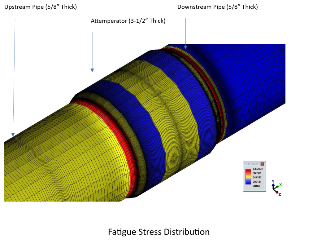
There are methodologies to evaluate these stresses in Section III and Section VIII of the ASME Boiler and Pressure Vessel Code. The limit on primary plus secondary stress range is usually set at about twice the yield strength at temperature to avoid ratcheting. The peak stress is evaluated by a fatigue analysis and provides a number of cycles, usually in terms of an allowable number of cycles. The following is a sample plot of the fatigue stress distribution for this particular case:

This desuperheater weld configuration was evaluated with a range of assumed temperature conditions bracketing the expected temperature conditions. The primary plus secondary stress range exceeds the allowable by a factor ranging from 3 to 5. The peak stress evaluation predicted the mean cycles to failure to be between 500 to 5000 cycles. These results clearly indicate that cracking would be expected. This sophisticated analysis confirms what one would expect using industry experience, although the design met the code, problems should be anticipated.
What mitigation or avoidance measures are available for problems like this? Simply imposing an artificially increased SIF would not work, because the stresses it would intensify are not the stresses that are causing the problem. Viable measures fall into two categories, either reduce the discontinuity, or reduce the temperature differences.
It is important to note that this configuration utilized standard weld end transition details that are customarily used with significant thickness transitions such as at valves. It is also important to note that there have been several instances of significant cracking in this area in various applications (especially in CSEF steels) throughout industry. In this particular case (grade 22 steel), we looked at several configurations as shown in Table 1. Changing the existing taper to a 3:1 taper reduces the secondary stresses by a factor of 1.2 to 1.3. It increases the mean cycles to failure by a factor of 2 to 2.5. These increases provide some improvement, but in this case, it would not be enough to prevent cracking. Changing the attemperator to one with 1” wall thickness reduces the secondary stresses by a factor of 1.7 to 2.0. It increases the mean cycles to failure by a factor of 5 to 7. These are significant increases, but in this this case, prevention of cracking is not assured. Changing the attemperator to 5/8” wall thickness to match the pipe reduces the secondary stresses by a factor of 2.2 and increases the mean cycles to failure by a factor of 12. These are significant increases, and cracking would no longer be expected.
| Table 1 | |||
| Primary Plus Secondary Stress | |||
| Base (B16.25)
stress ratio vs allowable |
3:1 Taper
Improvement Factor |
1” Thick
Improvement Factor |
5/8” Thick Improvement Factor |
| 3 to 5 | 1.2 to 1.3 | 1.7 to 2.0 | 2.2 |
| Primary Plus Secondary Stress | |||
| Base (B16.25)
Mean cycles to failure |
3:1 Taper
Improvement Factor |
1” Thick
Improvement Factor |
5/8” Thick Improvement Factor |
| 500 to 5000 | 2 to 2.5 | 5 to7 | 12 |
As mentioned previously, various temperature distributions were analyzed instead of determining the actual distribution.
- Reducing the internal temperature from the design temperature to the operating temperature reduces the secondary stresses by a factor of 1.6 and increase the mean cycles to failure by a factor of 4.1.
- Increasing the outside pipe temperature from 70 to 150 degrees with the internal temperature at operating, reduces the secondary stresses by a factor of 1.16 and increase the mean cycles to failure by a factor of 1.60.
- Reducing the temperature in the downstream half of the attemperator from 680 to 200 reduces the secondary stresses in the downstream connection by a factor of 5.7 and increase the mean cycles to failure by a factor of over 200.
To this end, possible ways of reducing the temperature gradients include:
- Incorporating preheating (either internally or externally) to reduce the temperature transients.
- Adding thermal sleeves to extend the temperature transition times and reduce the rapidity of transients.
- Revise operating procedures to reduce the temperature change rate.
In addition to the specific lessons learned, some general takeaways are:
- Just because a design meets code does not mean it is good.
- There is no substitute for experience.
- Sophisticated analysis and experienced judgment are both valid design tools. When they agree, then you can believe the results with great confidence. When they don’t, find out why.
