Hydroprocessing Relief Issues: Chapter 3 – Vapor and Liquid Blow-Through to Distillation
This is the third of 3 articles discussing relief issues for Hydroprocessing Units. Last month we discussed Separator Blow-through. As discussed, the five main lessons from that article are:
- Relief valves on low-pressure separators must be designed for vapor blow-through
- The design vapor blow-through rate must consider all potentially open level-control valves and bypass valves in the system
- The low-pressure separator must be able to contain the liquid surge from the high-pressure separator without filling up or carrying over liquid into the relief system
- Be cautious when using a chopper valve between the high-pressure separator level to prevent blow-through. Closing a chopper valve on the high-pressure separator oil outlet will likely cause a much bigger upset than vapor blow-through and could result in a loss of containment in the vapor relief system.
- Do not allow liquid or two-phase flow into the vapor relief system from a high-pressure unit.
These topics will be the subject of an AFPM Safety Bulletin to be released in 3Q, 2023
Overpressure on Distillation Columns from Reactor Loops
Distillation columns are an important part of hydroprocessing units – both for hydrocrackers and for hydrotreaters. There are 3 main concerns with distillation columns that are downstream of high-pressure reactor loops:
- Vapor blow-through from the final separator to the distillation column(s) potentially causing overpressure in the column(s).
- Vaporization of liquid in the distillation column adding to the vapor load for the distillation column relief valves.
- Liquid surge volume that can flow to the distillation column(s) even after feed is pulled from the reactor section.
From previous discussions, the amount of overpressure that can result in a rupture is shown in the table below:
Overpressure Consequences

Reference: API RP 581 Risk-Based Inspection Methodology, Table 6.14
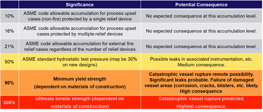
The table above shows that catastrophic vessel rupture is likely at 300% overpressure. Hydroprocessing units can have a final separator(s) operating at pressures exceeding 300 psig or more with distillation column(s) with design pressures less than 100 psig resulting in a potential overpressure of 300% or more.
Overpressure from vapor blow-through to distillation
As mentioned, the ratio of pressure between the final separator(s) and the distillation column(s) can be high enough to potentially cause significant overpressure and even rupture in the distillation section. Relief valves must be provided that are designed to handle the vapor blow-through from the separator(s). All sources of vapor blow-through should be considered to determine the total potential amount of vapor in a blow-through event.
Note that there may be multiple sources of vapor and liquid flowing to the distillation column. In the hydrocracker flow diagram below (Figure 1), the reactor section has both a cold, low-pressure separator, and a hot, low-pressure separator. In many units, liquid from knock-out pots could also flow to the distillation columns and provide a source of vapor blow-through.
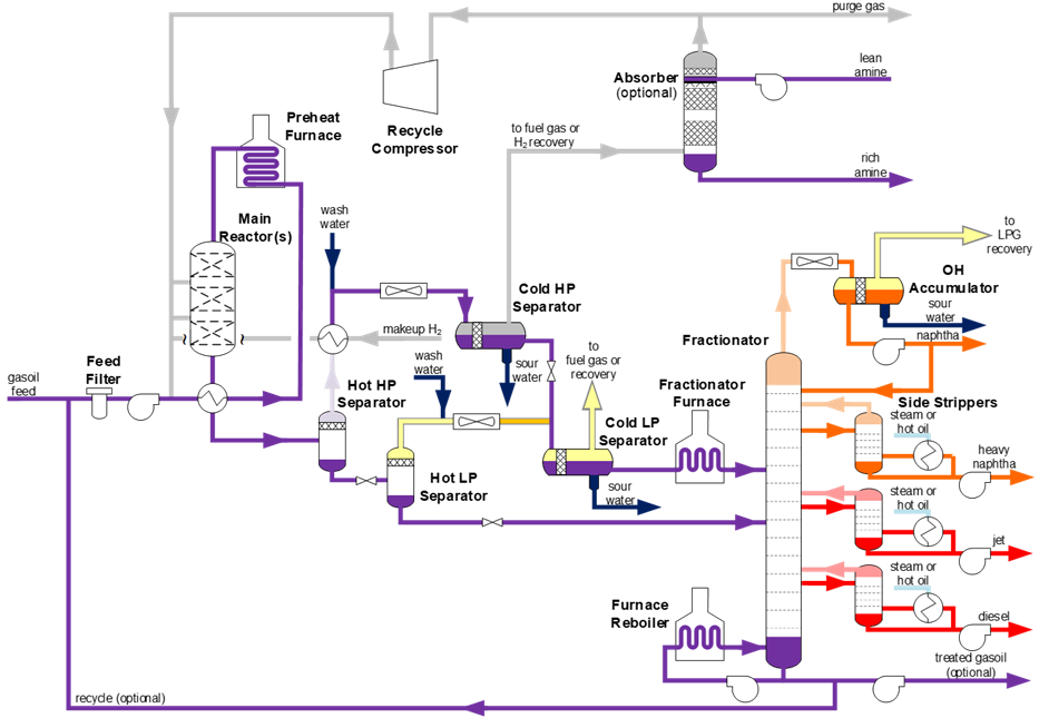
Figure 1 – Hydrocracker Process Flow Diagram with Hot and Cold Separators
Vaporization of liquid in the distillation column with vapor blow-through
When hydrogen gas is introduced to a distillation column, it acts like an inert gas by reducing the vapor pressure of the liquid in the column. Lowering the vapor pressure will cause vaporization of the liquid in the column, adding greatly to the vapor load on the relief valves.
All systems are different, but a simulation of a hydrocracker experiencing vapor blow-through of hydrogen rich gas showed that the presence of the hydrogen increased the vapor load on the relief valves by a factor of 5 times!
Therefore, the potential vaporization of liquid must be estimated and accounted for when sizing distillation column relief valves.
Surge volume of liquid flowing to the distillation column from the reactor section
One characteristic of hydroprocessing units is the reactor section holds a substantial amount of liquid during normal operation. In many units, the amount of liquid in the reactor section is more than the distillation column downstream of the reactor section can hold – even after feed is stopped to the reactor section.
Think about when you shut down the unit and strip all the liquid from the reactor – it often takes hours to get all the liquid out of the reactor.
In Figure 2 below, a diesel hydrotreater with a furnace reboiler column is shown as an example. To minimize the reboiler duty and distillation temperatures, stripping columns like the one shown are often operated at minimum pressures – typically less than 75 psig.
One scenario that has occurred in many hydrotreaters is a blocked outlet on the stripper bottoms to storage. A blocked outlet can result from pump failure or from a closed emergency block valve on the stripper bottoms. The pump can be spared to minimize the probability of a blocked outlet, but these pumps operate at very high temperatures, and I have seen multiple occurrences in the past when only one pump was available.
When a blocked outlet failure occurs, the stripper will fill up quickly from liquid flowing out of the reaction section. Even if the feed to the unit is cut, liquid will continue flowing from the reaction section for more than an hour. It is most likely that the stripper column will fill up.
Since the column operates at a low pressure, there may not be enough pressure to push the liquid out without an operating pump, so an alternate routing of liquid must be provided. Possible routings are:
- The relief valves on the column are sized to handle the liquid coming into the column.
- An alternate routing for liquid to a low-pressure system can be provided.
To fully evaluate this scenario, the total amount of liquid that can come out of the reactor section must be considered and a suitable outlet for the liquid flowing to the distillation column must be considered. This is one oversight that is frequently found in evaluating relief scenarios – not considering the total volume of liquid in the reactor system.
It may be easy to size the relief valves on the stripper to handle the liquid flow, but this amount of liquid flowing to the relief system will quickly fill up the relief drum, which requires adequate pumping capacity to keep the drum from overflowing to the flare.
Some units have provided alternate liquid routing to keep the distillation section from filling up and flowing to relief. If an alternate routing for the liquid is available, emergency procedures must be provided with clear direction on how the liquid is to be routed out of the distillation section. Emergency procedures should likely include the direction to pull feed from the reactor section.
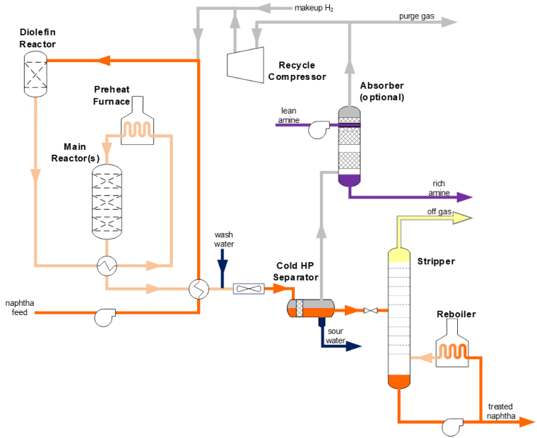
Figure 2 – Process Flow Diagram for a Diesel Hydrotreater
Summary of Lessons for Vapor Blow-through from final separators to distillation column(s)
- Relief valves must be provided on distillation columns to handle vapor blow-through from upstream separator(s).
- The relief capacity must include considerations for vaporization of liquid that will occur when hydrogen-rich gas blows through to the distillation column.
- Relief capacity and/or alternate liquid routing must be provided for the total volume of liquid that can flow from the distillation section.
Application in your unit(s)
- Have the relief valves in the distillation column(s) downstream of the reactor section been properly designed for vapor blow-through from the final separator(s)?
- Has the amount of liquid vaporization been estimated for a vapor-blow-through event and accounted for in sizing the distillation column relief valves?
- Have you considered the amount of liquid that can surge to the distillation column from the reactor section and provided a way to route the liquid out of the distillation column?
Have a question regarding your hydroprocessing relief issues? Feel free to drop us a line.

