Protection of Nuclear Power Plants from Tornado Missiles

Road Map of Regulatory Requirements
General Design Criteria – The protection of nuclear power plants from the effects of tornadoes (or extreme winds from typhoons or hurricanes, depending on the locality) is required through 10CFR50 Appendix A, 10 CFR 50, Appendix A, General Design Criterion 2 which requires that structures, systems, and components (SSCs) important to safety be designed to withstand the effects of natural phenomena such as tornadoes.
Standard Review Plan – The methods and criteria for the design of SSCs against the effects of tornadoes are addressed in the following Sections of NUREG-0800 (Standard Review Plan):
- Section 2.3.1 addresses regional climatology. This Section refers to RG 1.76 for the postulated design-basis tornado parameters.
- Section 3.3.2 addresses tornado loadings. This Section defines the three effects to be addressed:
- Tornado winds, considering translational and rotational wind speeds.
- Tornado-generated atmospheric pressure differentials across the interior and exterior of enclosed or partially-enclosed structures.
- Tornado missile impacts on exposed SSCs.
Regarding design rules, Section 3.3.2 refers to:
-
- ASCE-7 for calculating the wind pressure on SSCs.
- RG 1.76 and the textbook by Simiu and Scanlan for differential pressure loads.
- RG 1.76 and Section 3.5.3 for tornado missiles.
- Section 3.5.1.4 addresses missiles generated by tornadoes and extreme winds. This Section refers to RG 1.76 for tornado missiles and to RG 1.221 for hurricane missiles.
- Section 3.5.2 provides guidance to identify the SSCs that must be protected from externally-generated missiles.
- Section 3.5.3 addresses the barrier design procedures. This Section points out the need to address local effects and overall response (global effects):
Local Effects
-
- The local effects on concrete include penetration (crater) or perforation (full penetration), spalling (at the impact face) and scabbing (at the opposite face), this Section refers to the 1976 paper by R.P. Kennedy, the National Defense Research Committee (NDRC) formula, and it provides a Table of minimum concrete wall and roof thicknesses, by Tornado Region.
- For local effects on steel include penetration (crater) or perforation (full penetration), this Section refers to the 1959 Stanford Research Institute (SRI) empirical formula (Zabel et. al.), and the 1971 Ballistic Research Laboratory (BRL) empirical formula (Grabarek, BRL-MR-2134) if it leads to results comparable to SRI.
The SRI formula, as reported in the ORNL TID-4500, 1965, is in the form
$$E/(D F^2 )=S/46,500 (16,000 T^2/F^2 +375 (W T)/F^2 )$$
E = critical kinetic energy required for penetration, ft-lb
D = rod diameter, in.
S = ultimate tensile strength of target plate, psi.
T = target plate thickness, in.
W = length of side of square window in the target frame, in.
F = scale factor = W/WS; WS = 4 in.
The BRL formula, as reported in Grabarek, 1971, is in the form
$$(M 〖V_L〗^2)/D^3 =C ((T secθ)/D)^α$$
M = projectile mass
VL = limit velocity
D = projectile diameter
C,α = empirical best-fit parameter
T = target thickness
Θ = obliquity measured from plate normal
In tornado missile design practice, Θ = 0 (strike normal to the target) the BRL is used in the form
$$T=(((M 〖V_L〗^2)/2)^.67) /(672 D)$$
M = projectile mass, lbf.sec2/ft
VL = limit velocity, ft/sec
D = projectile diameter, in.
T = target thickness, in.
Global Effects
-
- For global effects on concrete or steel, this Section refers to the 1973 paper by Williamson and Alvy, with ductility capacities from N-690-1994 with 2004 supplement.
Regulatory Guide – RG 1.76 provides three key design inputs: The tornado wind speeds, the differential atmospheric pressures, and the characteristics of tornado missiles.
RG 1.76 Tornado Wind Speed and Pressure Drop: The tornado intensity regions for the contiguous United States for exceedance probabilities of 10-7 per year. Three Regions are defined:
-
- Region I, central US, at 230 mph (1.2 psi atmospheric pressure drop)
- Region II, eastern US and great plains, at 200 mph (0.9 psi atmospheric pressure drop)
- Region III, western US, at 160 mph (0.6 psi atmospheric pressure drop)
In all three cases, the translational speed is 20% and the rotational speed is 80% of the total speed.
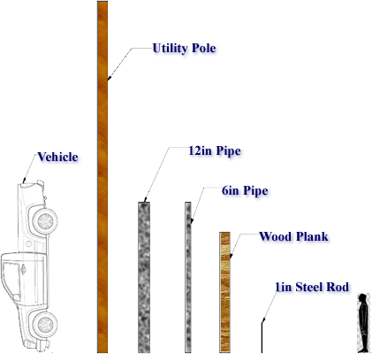
RG 1.76 Tornado Missiles – The tornado missiles are described as objects lying within the path of the tornado wind and debris of nearby damaged structures. The postulated types of missiles have changed over the years, as described in the Chronology below: Most plants were designed for a wooden plank, wooden telephone pole, two steel pipes, an automobile, and – for probing the potential for penetration – a 1 in. steel rod. In 2007, the 6 missiles were replaced by 3 missiles.
Assumptions for Tornado Missile Analysis
The postulation of missiles in accordance with RG 1.76, is a mixture of probabilistic and deterministic assumptions, which are not self-evident at first reading:
- Probabilistic: The wind speed which lifts and carries the postulated missiles is defined probabilistically, it corresponds to a tornado with a 10-7 exceedance probability per year.
- Conservative Deterministic: The missiles are assumed to start their motion from a point located on the tornado translation axis, at a distance downward of the tornado center equal to the radius of the maximum circumferential wind speeds.
- Conservative Deterministic: The speed with which a missile hits a target is assumed equal to the maximum speed that the same missile would attain if its trajectory were unobstructed by the presence of any obstacle.
- Probabilistic: The product of the drag coefficient multiplied by the missile area CD×A (which will control the missile speed and kinetic energy) is assumed to be an average corresponding to all positions statistically possible.
- Conservative Deterministic: The missiles are assumed to be non-tumbling, they have a constant body attitude, and they expose their largest surface normal to the wind velocity. This conservative assumption is “highly unlikely” (NBSIR 76-1050, 1976) and, for conservatism, contradicts the earlier probabilistic assumption of a tumbling CD×A.
- Conservative Deterministic: Not all postulated missiles can be lifted by tornado wind speeds in the range of 200 mph. McDonald et. al. (1976) conducted a computer simulation analysis of four missiles in a 210 mph tornado (1) a timber plank 4 x 12, 12 f t long at 139 lbs; (2) a steel pipe, Schedule 40, 3 in. dia., 10 f t long at 76 lbs; (3) a utility pole, 13.5 in. dia., 35 f t long at 1490 lbs; and (4) an automobile, 4000 lbs. The Results from the analysis showed that only the 4 x 12 timber plank would be sustained in the assumed windfield. The 3 in, dia. pipe and the utility pole were ruled out as potential missiles. The automobile was not sustained in the wind field, but would instead roll or tumble along the ground.
- Assumption: The vertical wind speed is assumed to be 2/3 the horizontal velocity, in RG 1.76 the value is rounded to 70%.
Below is a brief chronology of the design rules for tornado missiles in nuclear power plants.
|
Chronology Design of Nuclear Power Plants for Tornado Missiles |
|
| 1946 | The NDRC penetration formula is published by the National Defense Research Committee (NDRC) “Effects of Impact and Explosions”. |
| 1957 | The BRL perforation formula is published by Jameson and Williams, “Velocity Losses of Cylindrical Steel Projectile Perforating Mild-Steel Plates,” Report No. 1019,, Ballistic Research Laboratories, July, 1957 |
| 1963 | Recht and Ipson (University of Denver) publish “Ballistic Perforation Dynamics” |
| 1965 | Oak Ridge report ORNL/NSIC-5 publishes test-based penetration formulas for rod-shaped missiles in shells. The formula are still referenced in SRP 3.5.3 (2007). |
| 1969 | Westinghouse publishes “Characteristics of Tornado Generated Missiles” WCAP-7897. |
| 1971 |
Tetsuya Fujita introduces the Fujita scale to rate tornadoes. |
| 1972 | ANSI A58.1 “Building Code Requirements for Minimum Design Loads in Buildings and Other Structures” provided wind load criteria based on probabilistically determined wind speed and tabulated forms of design load parameters. Later, these rules were moved to ASCE 7. |
| 1973 | Williamson and Alvy publish “Impact Effect of Fragments Striking Structural Elements” which addresses the global effects of missiles on steel and concrete barriers. The formula are still referenced in SRP 3.5.3 (2007). |
| 1973 |
A report by Battelle Pacific Northwest Lab. BNWL-SA-4734; defines postulated tornado missiles:
|
| 1973 | Bechtel issues BC-TOP-9 Rev.1 |
| 1974 | The NRC issues WASH-1300 “Technical Basis for Interim Regional Tornado Criteria” which determines the design basis tornado wind speeds and pressure drops (not missiles) for the three regions (approximately I east and central, II mountain, III pacific). |
| 1974 | RG 1.76 “Design Basis Tornado for Nuclear Power Plants” provides the tornado wind speeds (based on WASH-1300, 1973), but does not specify tornado missiles. |
| 1974-1975 | MacDonald et.al. publish tornado design criteria for several DOE sites. They address the equations to evaluate local and global loads. They recommend the Ballistic Research Lab (BRL) formula for missile penetration in steel. They refer to BC-TOP-9 (1973) |
| 1974-1975 | The AE’s write their tornado missile analysis guides: Gilbert’s CAI-TR-102, TVA’s TVA-Tr74-1, Ebasco’s ETR-1003, Brown and Root’s U&R -001,Bechtel’s BC-TOP-9A, United Engineer’s UEC-TR-002-0, etc. |
| 1975 |
SRP 3.5.1.4 missiles generated by tornadoes Rev.0 Missile Spectrum A
Missile Spectrum B
These missiles are considered to be capable of striking in all directions with vertical velocities equal to 80% of the acceptable horizontal velocities. Missiles A, B, C, D, and E are to be considered at all elevations and missiles F and G at elevations up to 30 feet above all grade levels within 1/2 mile of the facility structures. |
| 1976 |
R.P. Kennedy publishes “A Review of Procedures for the Analysis and Design of Concrete Structures to Resist Missile Impact Effects” |
| 1976 | The National Bureau of Standards publishes NBSIR- 76-1050 “Tornado-Borne Missile Speeds”, which provides a model for the missile motion and presents the results numerical experiments are carried to corresponding to various assumptions on the initial conditions of the missile motion, the structure of the tornado flow, and the aerodynamic properties of the missile. |
| 1977 | EPRI issues NP-440 “Full-Scale Tornado Missile Impact Tests” (conducted at Sandia National Lab.). Four missiles were tested wooden utility pole (1500 lb.); 1-inch dia. steel reinforcing bar (8 lb.); 3-inch dia. steel pipe (78 lb.); 12-inch dia. steel pipe (743 lb.) onto concrete panels. |
| 1978 | SRP 3.5.1.4 missiles generated by tornadoes Rev.1 |
| 1981 |
SRP 3.5.1.4 missiles generated by tornadoes Rev.2 Spectrum I missiles are defined as: An 1800 Kg automobile, a 125. Kg 8″ armor piercing artillery shell, and a 1″ solid steel sphere, all impacting at 35% of the maximum horizontal windspeed of the design basis tornado. The first two missiles are assumed to impact at normal incidence, the last to impinge upon barrier openings in the most damaging directions. Alternately, Spectrum II missiles are defined as the missiles selected by the National Bureau of Standards as representative of construction site debris in report NBSIR 76-1050. Tornado regions are defined in WASH-1300: Missile; Mass (Kg); Dimensions (m); Velocity (m/sec) Region I / Region II / Region III A – Wood Plank; 52; .092 x .289 x 3.66; 83 / 70 / 58 Vertical velocities of 70% of the postulated horizontal velocities are acceptable in both spectra except for the small missile in Spectrum I or missile C above. These missiles, which are used to test barrier openings, should be assumed to have the same velocity in all directions. Missiles A, B, C, and E are to be considered at all elevations and missiles D and F at elevations up to 30 Feet above all grade levels within 1/2 mile of the facility structures. |
| 1996 | SRP 3.5.1.4 missiles generated by tornadoes Rev.3 draft |
| 2006 |
Draft RG 1.76 Rev.1 Draft introduces tornado design-basis wind speeds corresponding to the exceedance frequency of 10-7 per year are lower than those given in the original version of RG 1.76. The three new missiles are introduced (see 2007 RG 1.76 below). |
| 2006 | SRP 3.5.1.4 missiles generated by tornadoes Rev.3 second draft: deletes the characteristics of the postulated missile, and refers back to RG 1.76. |
| 2007 | SRP 3.5.1.4 missiles generated by tornadoes Rev.3 |
| 2007 |
RG 1.76 “Design Basis Tornado and Tornado Missiles for Nuclear Power Plants” A new set of tornado missiles is introduced: A 6 in. pipe, the automobile, and a 1 in. solid steel sphere (bullet-like, instead of the previous rod). The NRC considers the missiles listed in Table 2 to be capable of striking in all directions with horizontal velocities of VMh and vertical velocities equal to 67 percent of VMh . Barrier design should be evaluated assuming a normal impact to the surface for the Schedule 40 pipe and automobile missiles. The automobile missile is considered to impact at all altitudes less than 30 feet (9.14 meters) above all grade levels within 0.5 mile (0.8 kilometer) of the plant structures. Table 2 includes a different size and weight automobile for Region III than for Regions I and II. The heavier automobile used in the calculations for Regions I and II will have a lower kinetic energy in Region III. This effect is a consequence of the low maximum horizontal speed VMh of the heavier automobile in the Region III tornado wind field. |
| 2011 |
RG 1.221 “Design Basis Hurricanes and Hurricane Missiles for Nuclear Power Plants” Missile Type Dimensions Mass |
| 2013 | SRP 3.5.1.4 missiles generated by tornadoes Rev.4 draft |
| 2015 |
SRP 3.5.1.4 missiles generated by tornadoes Rev.4 Initiating frequency of tornado missiles is reported as 10-7 per year or greater |
| 2015 | The NRC issues a Regulatory Issue Summary (RIS) “Tornado Missile Protection” to remind licensees of the need to conform to the plants’ current, site-specific licensing basis for tornado-generated missile protection. |
Have a question or would like more information? You may post to this blog or click the link below for more help.
[readon2 url=”index.php?option=com_rsform&view=rsform&formId=4&Itemid=739&lang=en”]Request Info[/readon2]