ASME III Appendix F – A Valuable Guide to the Operability Assessment of Piping Systems
The NRC Inspection Manual Chapter 0326 refers to ASME III Appendix F as an acceptable method for the evaluation of “a degradation or nonconformance associated with piping or pipe supports …”. Appendix F provides five alternative methods for the qualification of pressure equipment, piping, and their supports. They are: (1) elastic analysis, (2) plastic analysis, (3) limit collapse analysis, (4) plastic collapse analysis, and (5) plastic instability analysis. Each of the five methods provides a different way of approaching the evaluation, with criteria that are specifically matched to the method. In this manner Appendix F reduces the conservatism inherent to the design analysis methods for normal operating conditions.
The Level D Service Limits and design rules contained in Appendix F are intended (F‑1200) to prevent the rupture of the pressure‐retaining boundary, but are not intended to assure operability of components during or following the specified event.
Following is a brief description of each of the five Appendix F methods, and how to implement them in practice. A comprehensive evaluation will consider all five methods and determine which criterion is the limiting condition. A more detailed coverage of operability analysis and the use of Appendix F is provided by George Antaki in his training course on this subject.
Implementation Overview
These methods are best performed using finite element analysis. First, you should review the capabilities of the software to determine if it supports the features and material models required to perform these analyses. Some software may require the explicit inclusion or activation of nonlinear geometric effects in the solution, where the solution step is updated based on the deformed geometry. This is likely to be trivial for the elastic case, but is important for all cases with plasticity as the deformations may be significant.
Appendix F does not specify the source for the plastic stress‐strain curve. One good source is ASME Section VIII, Division 2, Annex 3‐D.3, which provides equations to develop the curves for commonly used materials. Extra caution should be applied to avoid mixing engineering stress and true stress without appropriate translation. Note that the stress‑strain curves input into the FEA software are likely to be true stress‑strain, and either the results or the plastic evaluation criterion of Appendix F must be adjusted accordingly.
Apply the load in small increments so that the effects of increasing the load may be seen. The shape of the stress‑strain response and displacement‑vs‑load curves provide valuable insight into the behavior and failure modes of the system.
All elements of the system must be considered for evaluation of stresses, etc. However, experienced analysts can accurately predict where the limiting conditions may be found, and can focus their results extraction efforts at those locations. It may be necessary to apply stress intensification factors (SIFs) to piping components, or the software may evaluate the ovalization of piping directly.
Elastic Method
The elastic analysis method is described in Appendix F § F‑1330. This method is the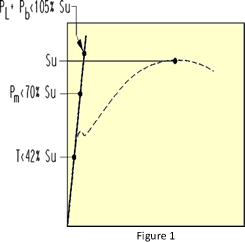 simplest and can be performed using hand calculations or almostany FEA software. The criteria for the elastic method are of a form similar to those used in design analyses, and are summarized as:
- Pm < 70% SU
- Pm + Pb < 105% SU
- t < 42% SU
This is the only method where linear scaling or extrapolation of a known load can be applied. Note that the elastic method does not address buckling or other large deformation failure modes.
Limit Method
The limit analysis method is described in ASME III Div. I Subsection NB § NB‑3213.27.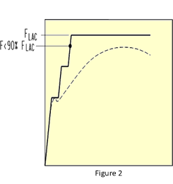 It considers the material to behave in an elastic-perfectly plastic manner. This method determines the load at which a plastic hinge occurs, and is well suited for analysis of compressive loads, or bending of pipe elbows and non‑compact beams. The allowable load is limited to 90% of the collapse load.
The material properties must specify the tangent modulus in addition to the Young’s modulus. For FEA software that support bilinear material property curves, the first entry is Young’s modulus, and the second entry is zero. A zero tangent modulus is perfectly plastic – the strain will increase with load but the stress will not (i.e. no strain hardening occurs). Obviously, the software must support plasticity ‑ some simpler analysis programs only support linear elastic analysis.
Collapse is shown by runaway displacement (NB‑3213.28) followed by solution non-convergence. The displacement over time should be reviewed to confirm that non-convergence does in fact occur due to collapse and not a numerical error in the model. Finding the collapse load may take some iteration to determine precisely. Instead of incrementing up the load, it may be most efficient to start by intentionally overshooting the limit, then observe the load at the time when the solution fails, and narrow in from there.
Plastic Methods
 The plastic analysis methods are described in Appendix F § F‑1340 and ASME III Div. I Subsection NB § NB‑3213.24 thru NB‑3213.26. The plastic analysis methods all require strain hardening material properties. There are three sets of plastic analysis criteria.
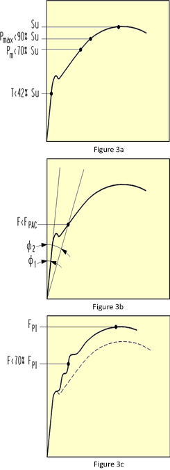
The first criterion (F‑1341.2) is simply labeled ‘plastic analysis’ and may be summarized as:
- Pmax < 90% SU
- Pm < 70% SU
- t < 42% SU
Note that the maximum stress criteria Pmax has a higher limit than the elastic method, which is enabled by using a more sophisticated analysis technique.
The second criterion (F‑1341.3 and NB‑3213.24) is labeled plastic collapse, and it can be described as the load causing deformation equal to twice the deformation at the onset of yield, which is equivalent to the load at the time the stress‑strain response curve intersects with a line having half the slope of Young’s modulus.
The third criterion (F‑1341.4) is labeled plastic instability, and it consists in finding the load at 70% of the maximum load supported by the system.
All three methods of plastic analysis can be performed with one run of the FEA model. You would run the model until all of the plastic analysis criteria are met or exceeded, which will be the instability condition (beyond which the analysis cannot continue to solve). The allowable load is the load applied at the time (i.e. solution substep) when a given criterion is reached.