Elevated Temperature Reactor Component Design and Qualification

Becht Engineering, Nuclear Services Division, has completed a finite-element numerical study of two proposed Code Cases for ASME III Division 1 Subsection NH, Class 1 Components in Elevated Temperature Service. They are:
“Satisfaction of Strain limits for Class 1 Components at Elevated Temperature Service Using Elastic-Perfectly Plastic Analysis” and
“Calculation of Creep-Fatigue for Class 1 Components at Elevated Temperature Service Using Elastic-Perfectly Plastic Analysis.”
Proposed Code Cases
These two proposed ASME III Code Cases provide methods and criteria for the prediction of the accumulated strain and creep-fatigue life evaluations for a nuclear component operating in the creep range, using elastic-perfectly plastic (EPP) models. Creep regime as considered in Subsection NH corresponds to components at temperatures above 700oF or 800oF depending on material. EPP-Strain and EPP-Creep-Fatigue are the abbreviated terms used for these two Code Cases in the following discussion. Subsection NH currently provides elastic, simplified elastic-plastic and inelastic methods for the evaluation of strain limits and creep-fatigue. These two proposed Code Cases – not yet approved by Code – provide an alternative to the simplified elastic-plastic methods currently in Subsection NH. EPP-Strain provides an alternative to NH-3252 and Subsection NH, Appendix T, NH-T-1320, NH-T-1330 and NH-T-1713. EPP-Creep-Fatigue provides an alternative to NH-3252 and Appendix T, T-1420, T-1430 and T-1715.
Strain and Creep Fatigue Criteria
The EPP analysis for elevated temperature involves the use of a pseudo yield stress (PYS). For the EPP-Strain Code Case the PYS is based on the isochronous stress strain data in Subsection NH. For the EPP-Creep-Fatigue Code Case the PYS is based on the minimum stress-to-rupture data in Subsection NH. The EPP analysis defined in the Code Cases is iterative, such that a target inelastic strain for the EPP-Strain Code Case or a trial time duration for the EPP-Creep-Fatigue Code Case is defined along with the total number of hours of operation above the elevated temperature. Iterations of EPP analyses are carried out on the modeled component until it no longer ratchets or shakes-down in accordance with the requirements of each of the Code Cases. The EPP-Strain Code Case requires demonstration of non-ratcheting, and the EPP Creep-Fatigue Code Case requires demonstration of shakedown.
The results from the EPP-Strain evaluation is a bounding accumulated strain for the modeled component. If the bounding strain meets the criteria of the EPP-Strain Code Case, then the component meets the strain limits requirement of Subsection NH. The results of the EPP-Creep-Fatigue evaluation is a bounding creep damage for the modeled component, which is then added to the bounding fatigue damage of the modeled component. The fatigue damage is computed on the resulting maximum equivalent strain range from the EPP-strain history resulting from the component that shakes down.
Features and Limitations
The principal features of the EPP method include:
- No reliance on stress classification or stress linearization.
- Bounding evaluation provides early design assessment of accumulated strain and creep-fatigue.
- Numerically simpler than complete inelastic analysis.
- Weld regions can be included as a separate material region with its PYS properties.
- Multiple material regions can be included, also with their PYS properties.
Notable Limitations of the method include:
- Does not provide a location-by-location assessment of creep-fatigue damage, i.e. it is the bounding creep-fatigue damage at the worst location within the modeled component.
- Time partitioning is not included in the currently proposed code case for the target inelastic strain because the target strain uses a single elevated temperature time parameter.
The numerical study is performed on a nozzle-to-sphere intersection, with time-varying internal pressure, time-varying nozzle end pipe loads, and time-varying thermal boundary conditions. A 316 Stainless forging material is used throughout the model, including in the weld region. However, different PYSs are used for the base metal and the weld metal.
EPP-Strain Evaluation Results
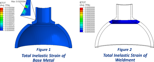
After three cycles, the change in plastic inelastic strain is zero. This indicates that non-ratcheting is achieved in accordance with the Code Case criteria. Figure 1 and Figure 2 show the resulting total inelastic strain for both the base metal and the weldment, which is achieved after the third pseudo yield stress (PYS) cycle. For this case, the base metal has a target inelastic strain of 1.00% and the base metal has a target inelastic strain of 0.50%.
EPP-Creep-Fatigue Evaluation Results
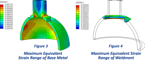
After three cycles, the change in plastic inelastic strain is zero. This indicates that the component meets the shakedown requirements of the EPP-Creep-Fatigue Code Case. Figure 3 and Figure 4 show the resulting maximum equivalent strain range corresponding to the achieved target creep strain for both the base metal and the weldment. The strain range time history is accordingly used to compute cumulative fatigue damage in accordance with Subsection NH-T-1413. The creep-fatigue damage is calculated in accordance with NH-T-1411.