Introduction to LOCA Blowdown Loads on Reactor Internals and Fluid-Structure Interaction
Design of a Nuclear Power Plant for a LOCA
Nuclear power plants are designed with the capability to safely shut-down following a number of hypothetical accident scenarios. One of those accidents is the rupture of a pipe in the reactor coolant system (RCS). Such a rupture would result in a loss of coolant accident (LOCA), which would challenge the plant in three ways:
- The pressurized cooling water, as it discharges from the break, will flash to steam. This would cause a harsh, hot, humid environment that will challenge the structures, systems, and components (SSCs) in the reactor building.
- The LOCA would cause the water from the broken pipe to discharge into the building instead of reaching the reactor core. This is why the RCS has redundant reactor coolant loops (RCL), and have the capability to inject additional coolant through the emergency core cooling system (ECCS). So, the ECCS is sized to make-up for the lost coolant water.
- The discharge of water from the break will cause dynamic effects on the RCL and the reactor pressure vessel (RPV). These dynamic loads are:
- A depressurization wave that will travel from the break, in both directions, causing unbalanced loads in the RCS and in particular on the RCL piping and the RPV and its internals and the fuel assemblies. These loads are called the LOCA blowdown loads.
- A strong jet of water and steam escaping from each side of the break. This jet will impinge on nearby SSCs. For breaks inside the reactor shield wall, for example breaks at the RCL-to-RPV nozzles, the jet may impinge directly on the RPV.
- The whipping of the broken pipe, which could impact nearby SSCs, unless the pipe is restrained by special-purpose devices called whip restraints.
- A rise of the pressure inside the compartment where the break occurs, causing pressure forces on the concrete walls.
In this article, we will limit ourselves to the first dynamic effect mentioned, the LOCA blowdown forces, which is listed as (3)(a) above. There are many good publications which address the loads caused by a postulated LOCA blowdown, in particular the US NRC’s NUREG-0609 (1981).
Postulated Breaks in the RCS
There are two groups of break locations that result in a LOCA:
- Breaks in the main RCL piping itself. For a pressurized water reactor (PWR) these breaks could be in the order of 30 inch in diameter. Approximately 10 locations are typically selected in the main RCL piping to postulate breaks.
- Breaks in the lines connected to the main RCL piping, these are called the auxiliary lines. For a PWR, these breaks could be in the order of 14 inch or less.
The LOCA blowdown loads depend on several factors, including the break area, the initial pressure and temperature before the break occurs, and the break opening time. The LOCA blowdown loads will, of course, be much larger if they result from the first group of breaks, the main RCL breaks, compared to breaks postulated in the smaller auxiliary lines. The LOCA blowdown loads are very fast, the most significant loads occur within 1 second of the instant the break is postulated to occur.
A plant that can be qualified for leak-before-break (LBB), only needs to address the smaller blowdown loads from the auxiliary lines breaks. LBB is the subject of a separate article.
LOCA Loads on the Reactor Pressure Vessel Internals
The decompression wave causes three types of forces on the reactor vessel, internals, and fuel assemblies: (1) Forces due to thrust force at the break, (2) forces due to the differential pressure as the decompression wave travels through the system, (3) forces due to drag, (4) forces due to friction.
- The forces on the pipe, at the break location, due to thrust are in the general form from the primary loops on the vessel nozzles for break R1 are due to the unbalanced pressure at the broken nozzle
Fnozzle=Po×Anozzle×Cthrust
Where Fnozzle is the axial pressure thrust force applied at the nozzle; Po is the initial steady state pressure at the break location, prior to break; Anozzle is the flow area at the break location; and Cthrust is a thrust hydraulic coefficient.
- The forces anywhere in the RCS due to the LOCA blowdown differential pressure is
F ∆P = ∆P × Aeff
Where FDP is the force due to differential pressure on a SSC inside the RCS; DP is the pressure differential across the SSC; and Aeff is the effective area of application of the pressure on the SSC.
- The drag force depends on the velocity of the fluid after the LOCA occurs, as the fluid blows-down across the SSC, and it has the general form
Fdr=Cdr × ρ × u2/(2×g)
Where Fdr is the drag force on the SSC; Cdr is the drag coefficient of the SSC; r is the fluid density at the discontinuity; u is the local flow velocity along or across the SSC; and g is gravity.
- The friction force across the SSC is also dependent on the flow velocity, and it has the general form
Ffr=(f × u2) × ρ × Acontact/(8 × g)
Where Ffr is friction force applied to the SSC; f is the averaged coefficient of friction; u is the average flow velocity along the friction surface; r is the fluid density at the discontinuity; g is gravity; and Acontact is the contact area over which friction applies.
These four types of forces are then fed into a structural model of the reactor vessel and internals to calculate the loads, deformations, stresses, strains on the RPV and internals, to evaluate whether they can safely withstand the LOCA blowdown effects. This structural analysis has to also account for the concurrent effects of other loads occurring at the same time, and in particular the assumption that the LOCA break could have been triggered by a safe shutdown earthquake (SSE) and would therefore have to be combined with the SSE. These load combinations are defined in each plant’s Final Safety Analysis Report (FSAR).
Fluid-Structure Interaction (FSI)
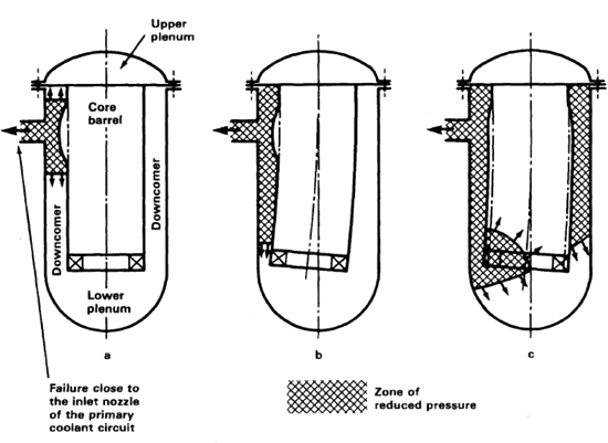
In a PWR, as the decompression wave progresses from a break on the side of the RPV inlet nozzle, it will enter the annular space between the reactor vessel and the core barrel, it will travel down to the lower internals, as it wraps around the barrel. This is nicely illustrated in the US NRC NUREG-0609 Figure 2, which is reproduced below.
As this decompression wave travels down the vessel-to-barrel annulus (middle sketch in figure below), and at the same time around the vessel-to-barrel annulus (last sketch in figure below), it will cause the core barrel (which contains the fuel assemblies) to deflect sideways towards the side of the decompression wave. This sideway deflection of the core barrel will in turn modify the blowdown pressures. This interaction between the fluid (the water that is being depressurized as a result of the break) and the structure (the core barrel moving sideways) is referred to vessel-to-barrel fluid-structure interaction (FSI). It can be summarized simply as follows: Initial blowdown pressure ® core barrel moves sideways ® blowdown pressure is reduced.
Not only does FSI reduce pressures and forces, it also slows-down the rate of oscillations of the LOCA pressures, so that with FSI the LOCA loads due to blowdown are lower and slower. This has been verified by large scale experiments conducted in Germany and documented in EPRI report NP-3677 (1984).