Recent Advances in Becht’s HTHA Damage Modeling Approach – Part 5: Time-Dependent Nelson Curves for Carbon and C-0.5Mo Steels

Overview
The first four parts of this series have described the updated Becht HTHA model and presented extensive validation for its application to Carbon Steel and C-0.5Mo. Based on this validation, time-based Nelson Curves for Carbon Steel (CS) and C-0.5Mo suitable for inclusion in API RP 941 [1] are now presented.
General Assumptions
Curves are generated for the PWHT and as-welded conditions, in both cases assuming failure by crack-like damage local to the weld. As described previously in this series, this corresponds to 100% damage to 25% of the wall thickness. This is conservative but appropriate since the factors that lead to distributed volumetric damage away from welds versus crack like damage near the weld are not always clear, or are seldom known before detailed metallographic examination.
The basic Nelson Curve does not correspond to a given damage depth – it is simply a collection of allowable pressure-temperature combinations. Therefore, for 100% damage at 25% depth, the pressure at that wall location could be used to enter the curve:
(PH2)depth = (PH2)surface . (1 – depth fraction)2
(PH2)25% = (PH2)surface . (1 – 0.25)2 = 0.563 . (PH2)surface
Where a parabolic pressure decrease through-wall is assumed. Rather than require the user to multiply the actual (surface) hydrogen partial pressure by 0.563 before reading off the allowable temperature, the Nelson Curves presented here are corrected to correspond to the 25% wall position directly. Curves for a given depth can be generated by finding the Nelson Curve temperatures at a given depth of the wall (using the partial pressure from the above equation) and then plotting those temperatures with the original (surface) pressures. The result is illustrated in Figure 1 for wall positions (depths) in 5% increments. As shown, as the hydrogen partial pressure decreases to zero, the curves converge to the same result, as expected.
Figure 1 and all curves presented in this part are based on 100% of the allowable stress at a given temperature, and a pressurized cylinder stress state. Additionally, each material class (CS or C-0.5Mo) uses the strongest typical material; specifically, SA-516 Gr. 70 for CS and SA-204 Gr. C for C-0.5Mo are chosen. While “strongest” would seem to imply best, the choice is conservative here because applied stresses are based on material strength and therefore will be maximized. With this background, time-based Nelson Curves for each material type (CS and C-0.5Mo) are now presented.
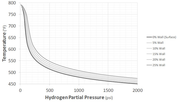
(SA-516 Gr. 70, 100% Allowable Stress, PWHT Condition (30% WRS), 100,000 hours)
Figure 1: Nelson Curves for Varying Wall Positions
Carbon Steel
Before presenting general carbon steel time-based Nelson Curves, 200,000 hour results for both PWHT and non-PWHT (as-welded) are compared to the existing API RP 941 curves. This is shown in Figure 2, where a typical carbon steel (SA-106 Gr. B) is used and the curves correspond to “failure” or 25% wall depth as described in the last section. As shown, the agreement is excellent. The most notable differences are the temperature cap at zero hydrogen partial pressure (which represents pure creep failure for the given time and applied stresses) and the curvature of the as-welded curve in the (mostly) horizontal portion of the response. This curvature is considered physical, and likely supported by API RP 941 plotted point 38 if normal operating temperature is used instead of the end-of-life (post filter addition) temperature as done currently.
This general agreement with existing practice for a reasonable time choice (200,000 hours) should give further confidence to the time-based results recommended here. The actual Carbon Steel time-based curves are shown in Figure 3 for the base metal or PWHT case and Figure 4 for the as-welded case. As discussed in the last section, these results conservatively correspond to SA-516 Gr. 70 and are generated directly using the model and constants described in the previous parts of this series and reference [2]. Times from 5,000 hours to 400,000 hours are provided and the existing API RP 941 carbon steel curves are also plotted for reference. At shorter times, possible “C-curve” type behavior has been suppressed such that allowable partial pressures are not allowed to increase with increasing temperature as an additional conservatism.
Finally, note that only minimum expected performance curves are provided for Carbon Steel, unlike C-0.5Mo which is presented next.
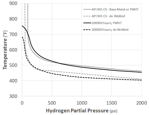
Figure 2: Carbon Steel 200,000 Results Comparison with Current API RP 941
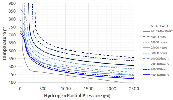
Figure 3: Recommended Carbon Steel Nelson Curves: PWHT
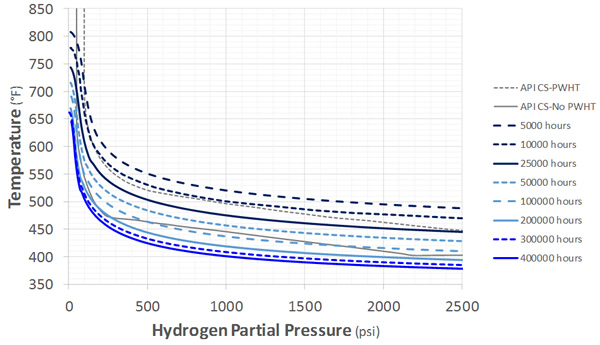
Figure 4: Recommended Carbon Steel Nelson Curves: As-Welded
C-0.5Mo
As discussed in Parts 2 and 3 of this series, C-0.5Mo HTHA performance is extremely variable. For this reason, both expected (or average) and minimum behavior are presented for both the PWHT and as-welded cases. Average and minimum have a statistical meaning here and per Part 3 of this series correspond to ac’s of 0.55 and 0.75 respectively where 0.55 is the actual mean value of the industry cases analyzed and 0.75 bounds 97.5% of the data. As before, PWHT represents the case of crack-like damage near the weld and the curves are generated with the same model and constants described earlier in this series. C-curve behavior is also again suppressed. The results are shown in the following figures:
-
- PWHT, Average Performance (ac = 0.55): Figure 5
- PWHT, Minimum Performance (ac = 0.75): Figure 6
- As-Welded, Average Performance (ac = 0.55): Figure 7
- As-Welded, Minimum Performance (ac = 0.75): Figure 8
As stated previously, all results are conservatively (from an applied stress perspective) based on SA-204 Gr. C temperature dependent strengths.
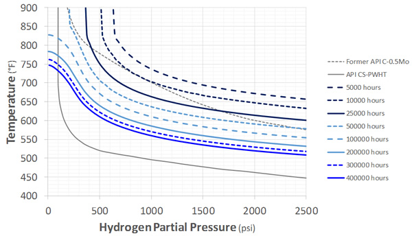
Figure 5: Recommended C-0.5Mo Nelson Curves: PWHT, Average Performance
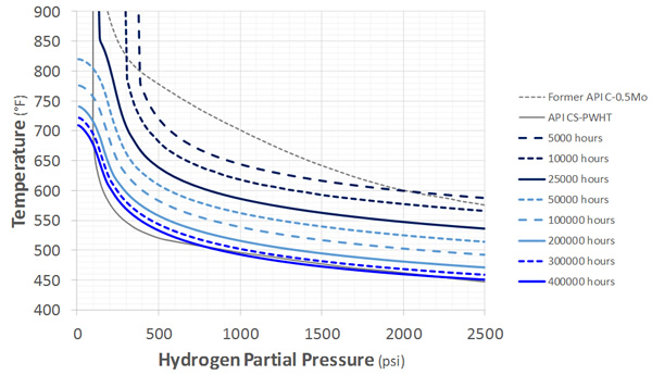
Figure 6: Recommended C-0.5Mo Nelson Curves: PWHT, Minimum Performance

Figure 7: Recommended C-0.5Mo Nelson Curves: As-Welded, Average Performance
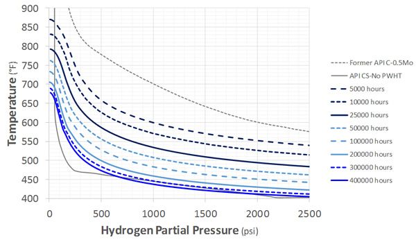
Figure 8: Recommended C-0.5Mo Nelson Curves: As-Welded, Minimum Performance
Concluding Comments
This blog is the culmination of the first four parts of this series and has presented time-based Nelson Curves based on calibration to nearly 100 total case histories, the vast majority representing actual component long term operation. In that sense, the calibration captures the variability in material processing, chemistry, fabrication details, weld quality, design and operating variations inherent in the industry data itself. Further, it seems likely that reported performance would be biased to under-performing cases and as such may have a further conservative bias.
Every effort has been made to provide accurate and meaningful results, and to base them on an analytical model with enough of the relevant physics to make interpolation and extrapolation possible. At the same time, the calibration is limited by any limitations, uncertainties or errors present in the data, and despite the multiple conservatisms discussed in this series, HTHA resistance of carbon and low alloy steels remains a research area and care is needed in any assessment.
The model presented in this series and introduced in [2] is only part of the solution and should never be used in isolation from materials, inspection and process expertise in addressing a given component. Many of the critical considerations were given in [3] and remain essential to a reliable and conservative estimate of performance, particularly given the consequence of failure of equipment in hydrogen service. Indeed, risk is also a key part of the assessment.
With this in mind, it is hoped that the time-based curves provided here can be part of a useful and impactful multidiscipline solution to the HTHA reliability issues that challenge industry.
References
- API Recommended Practice 941, “Steels for Hydrogen Service at Elevated Temperatures and Pressures in Petroleum Refineries and Petrochemical Plants,” Eighth Edition, February 2016. The American Petroleum Institute.
- Dewees, D., G. Buchheim, J. Staats and C. Becht V, “Practical HTHA Experience and Time-Based Nelson Curves for Improved Equipment Life Management,” Inspectioneering, V(26)-2. March/April 2020.
- Buchheim, G. “A new practical method for prioritizing equipment in HTHA service for inspection and replacement and the challenges in obtaining process conditions to be used in the HTHA Assessment,” Inspectioneering, V(20)-6. November/December 2014.
To gain more insight into this process or request information, please contact Gerrit Buchheim in the Corrosion and Materials Group by clicking below:


Excelent !