Crane Bridge Design
The CMAA Standard for Cranes: Becht Engineering recently completed the structural analysis for a single girder 5-ton crane bridge with an under-running hoist per CMAA-74 for nuclear waste handling operations. CMAA is the Crane Manufacturers Association of America, and CMAA-74 is the Specification for Top Running and Under Running Single Girder Electric Traveling Cranes Utilizing Under Running Trolley Hoist. The scope of CMAA-74 covers the crane classification, structural design, mechanical design, and electrical equipment. The scope of CMAA-74 points to supplementary design codes, such as the building code (ASCE-7), and crane maintenance standards (ASME B30.11, ASME B30.17). CMAA-74 provides the design loads and criteria for the structural, mechanical and electrical crane components.
Design Loads: Several structural factors must be addressed in the analysis and qualification of the crane bridge. They include the crane rated load and the number of load cycles. Designing the crane per CMAA-74, the number of cycles determines the service class and the life of the crane bridge. The loads applied to the crane bridge are normally deadweight, the payload (rated load), inertial effects due to motion, skewing loads, seismic, and, if outdoors, the wind loads. Dead weight for a single girder bridge beam can be applied at the center of gravity. The payload is the maximum permitted pick load. Hoists that fully or abruptly engage at the start of the lifting process increase the hoist payload from inertial effects by 50%. For this reason, variable speed hoists are advantageous since they start slowly and gradually increase their speed, therefore reducing the payload inertial effects.
Horizontal impact loads account for the possibility of the trolley or the crane bridge running into their respective bumper stops. For outdoor cranes, wind loads can be a source of serious accidents, and the crane must be designed, operated and parked taking into account the wind loads.
Structural Qualification: The stresses throughout the structure and at the connections are evaluated against limits. Typically, the hoists’ trolley deadweight and payload are combined to obtain a worst case bending stress on the bridge beam, which is typically located at the center of the bridge span. The flange local buckling due to the trolleys’ wheel load is reviewed and its stresses are added to the respective component stresses.
Another important consideration is preventing the bridge from derailing, including the case of the trolley impacting its stops. The end truck wheels typically have flanges on both sides to stay on the track. Another means of preventing derailing is to have a stop tab that runs below the runway I-beam such that it limits uplift and prevents the crane from derailing. If there is a misalignment either between the two end trucks or the two runway beams, the wheels can lock up and can cause weak axis bending for the bridge beam.
When the crane is located outdoors, it is designed for location-specific maximum wind loads, and the structure’s natural frequencies are reviewed to prevent the wind gusts and vortex shedding from exciting the crane at its natural frequencies. The crane is typically load tested at 125% of the rated load.
In summary, a good crane bridge design is critical since the crane loads are large and cyclic, and a component failure could affect life, safety, equipment, and in some cases the environment. It is therefore important to ensure that all of the bridge components are correctly designed for the applicable loads, following the methods and criteria outlined in CMAA-74 and referenced standards.
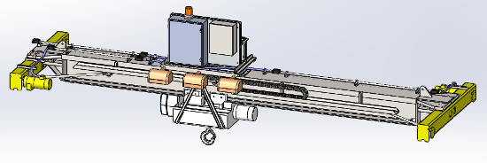
Figure: Five-Ton Indoor Top Running Single Girder Crane Bridge with Underslung Hoist





Hi, Michael. The ‘runway beam’ for my (Subject) crane is hung from the reinforced-concrete roof of a building. There are no calcs, specs, drawings, etc. for this support structure (i.e., post-installed anchors, & variety of structural steel shapes & welds that comprise the ‘gravity’ hangars & lateral bracing).
The ’14 annual inspection revealed that some of the post-installed anchors can’t be torque (i.e., they spin freely). A follow-up inspection revealed weld defects. The crane was taken out of service at this time.
Records indicate that the crane was ‘100% load tested’ in ’91; however, it is not known whether or not the existing support structure was in place at that time. Finally, the local crane subject matter expert has witnessed a) the safe movement of 1800 lbs the same week the ‘spinning anchors’ were discovered, & b) the safe use of the crane many times each week, over the past several years, w/loads on the order of 1600 lbs.
The crane owner would like to be able to start using the crane again. Although the crane isn’t needed to move anything close to 5 tons, the owner would like to be able to continue to treat the crane as a 5-ton crane (i.e., so that moving something like 1 ton is 20% of the crane’s rating vs something much larger than that).
What steps would you recommend for getting crane back in service?
Thanks,
Glen
Glen,
To get the crane back in service you need to do the following three things:
1- Reconstitute the design analyses and show compliance to the standard
2- Inspect and repair the damage
3- Load test the crane assembly to the requirements of the design code/standards.
Regards,
Michael Shipley
what the service factor to design travelling gear box of overhead crane?
where can i learn more abut overhead crane gearbox?
thank
Rashed,
On the overhead cranes that I have performed the stress analysis, the manufacturer of the crane procured pre-certified gearboxes. See the crane codes such as CMAA-74 (2010) for design guidance. Gearing is addressed in Section 4.2.
I would recommend a procuring a commercial gear box that is prequalified.
Regards,
Michael Shipley
There are many important factors to consider when designing the crane, as it matters a lot to get a right and suitable crane for material handling work. Very helpful information on the crane design and thanks for sharing this. I am looking forward to knowing more about the cranes from your new posts. 😀