Design/Specification of FCC Replacement Parts and Upgrades

Overview
Fluid Catalytic Cracking (FCC) units were first developed in the 1930s. Over the years this technology has evolved and it is one of the most important processes used in refineries. The FCC units are used to convert high boiling point, high molecular weight hydrocarbon fractions of crude oils to gasoline, olefinic gases, and other products.
There are a number of process technology providers who license proprietary FCC technology; however, the equipment is basically the same ─ a reactor vessel where the hydrocarbon feed and hot catalyst contact and react (~950F) producing hydrocarbon vapors for further processing, and a regenerator vessel where the carbon laid down on the surface of catalyst from the reaction is burned off (regenerated and heated) in a fluidized bed (~1350F). The regenerated catalyst is returned to the reactor. The catalyst circulation between the reactor and regenerator is continuous. Large diameter refractory lined piping (transfer lines) circulate the catalyst back and forth between the reactor and regenerator. Flue gas produced from combustion of the carbon in the regenerator is used to generate steam in a waste heat boiler or used in a flue gas expander to generate power or shaft horsepower. There are many complex internal components within the vessels and other components described above; e.g., cyclones to separate the catalyst from the flue gas, grids to distribute the combustion air into the regenerator, transfer lines to transport the catalyst, and slide valves to control catalyst flow. These FCC units operate at high temperature and require the use of high alloy steels, insulating and refractory linings to conserve heat, and to protect the vessels and internals from catalyst erosion (wear) and high temperature corrosion.
FCC run-lengths between maintenance outages (turnarounds), once measured in months, is now four years or more today. Improvements in FCC process technology, materials of construction, refractory improvements and installation methods, and improved capabilities to design and analyze internal components operating at high temperatures, have contributed to longer run-lengths. In the past, much of the mechanical design of FCC internals was based on good experience; i.e., what worked irrespective of what the analysis might show. The advances in analysis tools, e.g., non-linear finite element stress and heat transfer analysis (FEA) and computing power made it possible to analyze complex components. Research in high temperature behavior of materials operating in the creep range (~1000F and above) helped explain why experienced based designs worked and made it possible to look at higher temperature operation.
Turnaround planning usually begins 18 months to 24 months in advance. Worklists are developed based on past experience of the types of repairs/replacements expected; e.g., transfer line expansion joint replacement, air grid distributor repair/replacement, and component materials upgrades to improve reliability. Many of these components are long delivery items and require the development of detailed specifications for obtaining bids, and once purchased require follow-up of the detailed engineering; i.e., calculations and drawing reviews.
At Becht Engineering we have worked with a number of refineries to write mechanical specifications for the various components in FCC units and followed their designs through the detailed engineering and installation phases. Several recent examples are discussed below.
Piping Flexibility Analysis of Transfer Lines
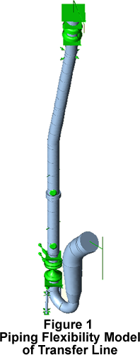
The transfer lines were designed with expansion joints and these joints were to be replaced during turnaround. Piping flexibility analyses were done to determine the expansion joint movements and these movements along with other design details were used in the development of a mechanical specification. The specification was used to obtain vendor bids. Also stress compliance of the lines with ASME B31.3 Process Piping Code was checked. As the transfer lines are generally refractory lined (cold wall) design, the refractory stiffness was included in the piping flexibility analysis. Figure 1 shows a typical transfer line outline.
Redesign of Spent Catalyst Riser
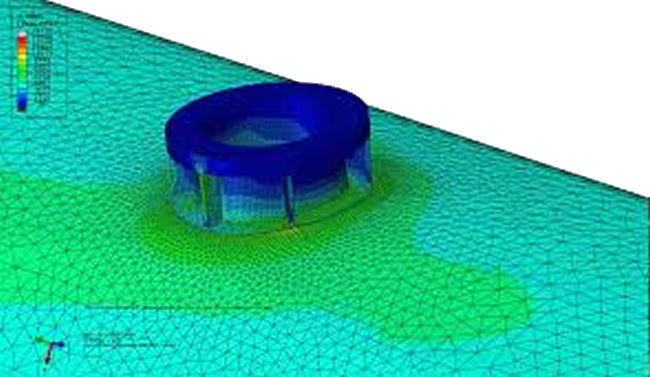
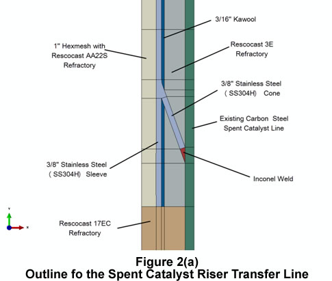
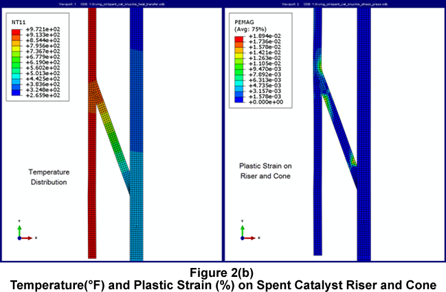
The spent catalyst riser transfer line was upgraded from the carbon steel material to stainless steel to improve the reliability. Figure 2(a) shows the outline of the new modified riser sleeve details. Steady state heat transfer analysis was done to determine the temperature of the riser sleeve and then the temperatures were then used for the stress analysis. Figure 2(b) shows the temperature distribution and the plastic strain calculated on the model. From the analysis it was concluded that the new re-design is satisfactory.
Regenerator Air Distribution Grid Design
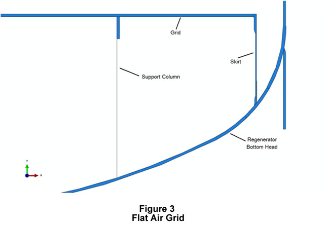
There are number of different air grid designs for the FCC regenerator. They are mainly, dome grid with skirt, flat grid with skirt, and pipe grid. All of these grids require detailed stress analysis to calculate the appropriate thicknesses. Most grids operate at high temperature (~1350F) and also have to be designed for different load combinations, startup, operation and upset conditions. Becht Engineering has analyzed grids for load combinations using finite element method and using allowable stress bases for high temperature design using the life fraction approach, i.e. what fraction of the design life is consumed under the various loading conditions.
Have a question or would like more information? You may post to this blog or click the link below for more help.
[readon2 url=”index.php?option=com_rsform&view=rsform&formId=4&Itemid=739&lang=en”]Request Info[/readon2]

